
Related Manuals for LMI Diamonback


Summary of Contents for LMI Diamonback
- Page 1 DIGITAL INDICATOR USER MANUAL LMI Corporation Linear Measurement Instruments 101 N. Alloy Drive Fenton, MI 48430 810-714-5811 www.lmicorporation.com www.lmicorporation.com...
-
Page 2: Table Of Contents
8.4 ZERO/ABS – MEASUREMENT MODES………………………………. 8.5 SETTING THE PRESET VALUE………………………………………… 8.6 TOLERANCE JUDGEMENT MODE……………………………………… 14 8.7 SETTING/CHANGING THE TOLERANCE……………………………… 8.8 SENDING DATA…………………………………………………………. 8.9 LOCKING…………………………………………………………………. CONNECTIONS/CABLE SPECIFICATIONS………………………………. 16-19 9.1 WIRELESS OPTION………………………………………………………. WIRELESS INDICATOR ADDENDUM…………………………………….. Copyright 2012 LMI Corporation Ver 3.0 6/29/2012 www.lmicorporation.com... -
Page 3: Introducton
SECTION 1: INTRODUCTION First of all LMI would like to thank you for purchasing a Diamondback Series digital indicator. LMI values every customer and we look forward to working with you and serving your measurement needs. We appreciate your feedback and strive to provide the highest customer satisfaction with every tool we sell. -
Page 4: Precautions
1.5 PACKAGING CONTENTS The package should be inspected immediately to verify that all of the parts are accounted for and no damage exists. If anything is missing or damaged, contact LMI Corporation immediately. The package should consist of the following:... -
Page 5: Overview
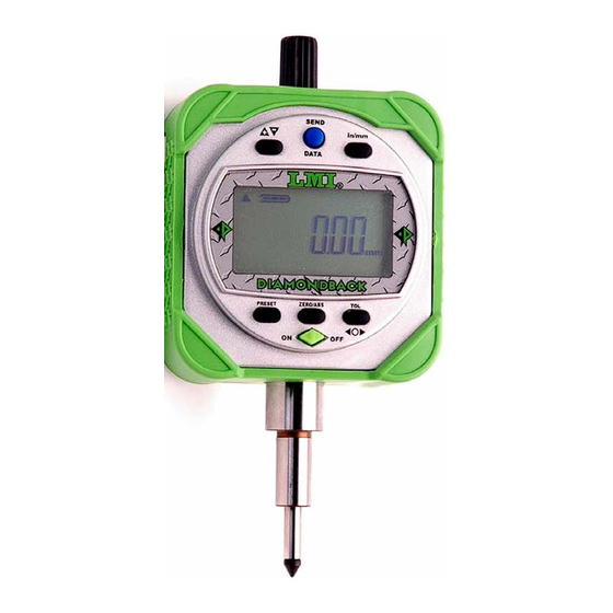
SECTION 2: OVERVIEW 2.1 INDICATOR OVERVIEW AND DIMENSIONS 1. Top Cap 7. Contact Point 2. LCD Screen 8. Battery Cover (2) 3. Function Keys 9. Mounting Lug (optional) 4. Protective Boot 10. USB Port 5. Stem 11. Serial Port and Digimatic Port 6. -
Page 6: Operating Keys Overview
2.2 OPERATING KEYS OVERVIEW: +/-: toggles between negative and positive values and changes the counting direction 15. SEND DATA: sends data through the output ports Serial/Digimatic or USB 16. in/mm: toggles between inches and millimeters 17. PRESET: recalls and resets a reference value 18. - Page 7 ½” Travel Indicator Dimensions Measuring Model Travel Resolution Accuracy Force LMI D-Back ½” .0005” .0004” 1.0N or 5.77” 31.0 3/8” 5335 12.7mm .01mm .01mm less 146.6mm LMI D-Back ½” .0005” .0004” 1.0N or 6.52” 50.0 3/8” 5355 12.7mm .01mm .01mm less 165.6mm...
- Page 8 1” Travel Indicator Dimensions Measuring Model Travel Resolution Accuracy Force LMI D-Back 1.0” .0005” .0008” 1.9N or 6.27” .53” 31.0 3/8” 1335 25.4 mm .01mm .02mm less 159.3mm 13.3mm LMI D-Back 1.0” .0005” .0008” 1.9N or 7.02” .75” 50.0 3/8”...
-
Page 9: Batteries
SECTION 3: BATTERIES 3.1 BATTERY ICON FULL 2/3 Capacity 1/3 Capacity DEPLETED Replace Battery The battery icon indicates the condition of the batteries in the unit. The battery power level is divided into three segments (see illustration above). As the batteries are depleted the display will change as illustrated above. -
Page 10: Optional Contact Tips
4.1 OPTIONAL CONTACT TIPS LMI offers a variety of optional tips to fit the Diamondback Series indicators (LMI 037 Tip shipped standard on all Diamondback models). Each model is designed to be virtually indestructible by using our unique two piece construction. These durable tips come in #4- 48UNF and M2.5x0.45 threads. -
Page 11: Protective Boot
SECTION 7: PROTECTIVE BOOT 7.1 REMOVING THE PROTECTIVE BOOT It may be necessary at some point to remove the protective rubber boot. Follow the steps below to properly remove the boot. To replace the boot simply reverse the steps. Step #1 – Unscrew and remove the top cap Step #2 –... -
Page 12: Operating Procedures
SECTION 8: OPERATING PROCEDURES 8.1 ON/OFF To turn on the indicator, press and release the ON/OFF button. To turn off the indicator, press and release the ON/OFF button. The digital indicator will turn on in the same mode it was in before it was turned off and the selected values for tolerance and preset will be kept. -
Page 13: Zero/Abs - Measurement Modes
8.4 ZERO/ABS – MEASUREMENT MODES ZERO Mode The digital indicator has two modes to take measurements. ZERO Mode (also known as INCremental Mode) is used to take measurements from a value of zero. ABS or Absolute Mode is used to take measurements from a Preset value. -
Page 14: Tolerance Judgement Mode
8.6 TOLERANCE JUDGMENT MODE Tolerance Judgment Mode will display whether the measured value is within the tolerance limits that have been set by the user. The TOL icon will display in the bottom right hand corner of the LCD when in Tolerance Judgment Mode. There are two different ways of viewing the Tolerance Judgment Mode, with and without numerical values. -
Page 15: Setting/Changing The Tolerance
8.7 SETTING/CHANGING TOLERANCES LIMITS To enter the mode that changes the tolerance value, Press and hold the TOL button for 3 seconds. The previously set value will display. The default values are +2.00mm and -2.00 mm. Press and hold the TOL button until the underscore is below the digit you would like to change. Press and release the TOL button to change the value of the digit to the desired value. -
Page 16: Sending Data
8.8 SENDING DATA The digital indicator can send data by USB, Digimatic, or RS232. The ports to connect the cables are located on top of the indicator. Please see SECTION 9 for specific details on connections. Remove the rubber cap off the connector that is to be used. Plug in the corresponding plug to the connector. -
Page 17: Connections/Cable Specifications
There are three methods that can be used for transferring data from the unit to a base unit, such as a PC. The methods for transferring data are USB using the LMI 6026 cable, Digimatic using the LMI 6028 cable and RS232 using the LMI 6027 cable. - Page 18 The RS232 port is used to connect the digital indicator directly to a PC COM port. For this type of connection, an LMI 6027 cable will be required. The cable will plug into the top right hand port. Align the triangles icons marked on the connector and the indicator.
-
Page 19: Wireless Option
9.1 WIRELESS OPTION (via add-on Mobile Module) An add-on wireless module is available from LMI to send data wirelessly to a PC. The wireless module plugs directly into the serial port on the indicator and attaches to the back of the indicator. -
Page 20: Wireless Indicator Addendum
10.0 WIRELESS INDICATOR ADDENDUM The LMI Wireless Digital Indicator can send readings to a PC via a MicroRidge Mobile Collect USB Base unit. No add-on modules or cables are needed because the wireless is built directly into the Diamondback Indicator.
Need help?
Do you have a question about the Diamonback and is the answer not in the manual?
Questions and answers