
Related Manuals for EuroLite VLS-800RBP


Summary of Contents for EuroLite VLS-800RBP
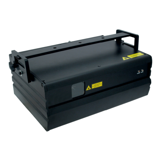
- Page 1 BEDIENUNGSANLEITUNG USER MANUAL VLS-800RBP Showlaser © Für weiteren Gebrauch aufbewahren! Copyright Keep this manual for future needs! Nachdruck verboten! Reproduction prohibited!
-
Page 2: Table Of Contents
Diese Bedienungsanleitung gilt für die Artikelnummer 51741450 This user manual is valid for the article number 51741450 Das neueste Update dieser Bedienungsanleitung finden Sie im Internet unter: You can find the latest update of this user manual in the Internet under: www.eurolite.de 2/15 00064217.DOC, Version 1.1... -
Page 3: Einführung
- sich die letzte Version der Anleitung im Internet herunter laden 1. EINFÜHRUNG Wir freuen uns, dass Sie sich für einen EUROLITE VLS-800RBP Laser entschieden haben. Wenn Sie nachfolgende Hinweise beachten, sind wir sicher, dass Sie lange Zeit Freude an Ihrem Kauf haben werden. -
Page 4: Bestimmungsgemäße Verwendung
Beim vorliegenden Produkt handelt es sich um einen betriebsfertigen Showlaser, dessen sichtbare Strahlung im Wellenlängenbereich von 400 bis 700 nm liegt, und der Lichteffekte für Unterhaltung etc. erzeugt. Beim Betreiben einer Laser-Einrichtung können Personenschäden hervorgerufen werden. Bitte beachten Sie unbedingt den Abschnitt "Rechtliche Hinweise" und "Schutzmaßnahmen für den sicheren Betrieb". Halten Sie das Gerät von Hitzequellen wie Heizkörpern oder Heizlüftern fern. - Page 5 Anzeige Der Unternehmer hat den Betrieb von Lasereinrichtungen der Klassen 4 dem zuständigen Unfall- versicherungsträger und der für den Arbeitsschutz zuständigen Behörde (Gewerbeaufsicht) vor der ersten Inbetriebnahme anzuzeigen. Die Anzeige soll folgende Angaben enthalten: Hersteller der Lasereinrichtung, Laserklasse, Strahlungs- leistung bzw. -energie, Wellenlänge(n), gegebenenfalls Impulsdauer und Impulswiederholfrequenz. Für Lasereinrichtungen der Klasse 4 ist die Einhaltung der maximal zulässigen Bestrahlung (MZB) für alle vorgesehenen Effekte durch ein Gutachten eines Sachverständigen nachzuweisen, sofern Laserstrahlen in Bereiche eindringen können, in der sich nicht unterwiesene Personen aufhalten.
- Page 6 Beispielsammlung – Explosionsschutz-Richtlinien – (EX-RL)“ (GUV 19.8), insbesondere Abschnitte E 2.3.9 und E 2.3.10. EUROLITE liefert mit dem vorliegenden Gerät einen betriebsfertigen Showlaser aus. Durch die Installation vor Ort wird ein Lasergerät oder ein Verbund von mehreren Lasern zu einer sog. Showlaseranlage.
-
Page 7: Rechtliche Hinweise
Inbetriebnahme Lasereinrichtungen müssen entsprechend ihrer Klasse und Verwendung mit den für einen sicheren Betrieb erforderlichen Schutzeinrichtungen ausgerüstet sein. Nehmen Sie das Gerät erst in Betrieb, nachdem Sie sich mit seinen Funktionen vertraut gemacht haben. Lassen Sie das Gerät nicht von Personen bedienen, die sich nicht mit dem Gerät auskennen. Wenn Geräte nicht mehr korrekt funktionieren, ist das meist das Ergebnis von unsachgemäßer Bedienung! Beachten Sie bitte, dass eigenmächtige Veränderungen an dem Gerät aus Sicherheitsgründen verboten sind. -
Page 8: Schutzmaßnahmen Für Den Sicheren Betrieb
Der Geschädigte selbst kann auf Schmerzensgeld klagen. Dadurch entstehende (wirtschaftliche) Schäden können durch eine zivilrechtliche Klage vom Bediener der Laser-Einrichtung eingefordert werden. Bitte beachten Sie: EUROLITE haftet nicht für Schäden, die durch unsachgemäße Installation und nicht bestimmungsgemäßen Betrieb verursacht werden! Schutzmaßnahmen für den sicheren Betrieb Für die Erzeugung und Anwendung von Laserstrahlung sind die Sicherheitsvorkehrungen aus DIN EN... -
Page 9: Sachwidrige Verwendung/Verhalten Im Störfall
Die Lasereinrichtung darf nur befugten Personen zugänglich sein. Der Showlaser darf niemals unbeaufsichtigt betrieben werden! Während einer Veranstaltung dürfen an Laseranlagen keine Reparaturen oder sonstigen Verrichtungen wie Neueinstellungen oder Korrekturen am Strahlverlauf vorgenommen werden. Außerhalb der eigentlichen Laser-Show ist der Strahl möglichst nahe am Laser zu unterbrechen oder abzuschalten. -
Page 10: Gerätebeschreibung
4. GERÄTEBESCHREIBUNG 4.1 Features Rot-blau-violetter Showlaser • Laser der Klassifikation 4 • Rot, blau, violett Farbmischung • Funktionsmodi: ILDA, DMX512, Auto, Sound-Aktiv • Effekte: Ebenen, Gitter, Tunnel, Welleneffekte, Schriften, Grafiken, Animationen • Laser-Diode: 650 nm rot, 450 nm blau • Für DMX-Betrieb auf der Geräterückseite: X und Y Größeneinstellung •... - Page 11 Die Installation muss immer mit einer zweiten, unabhängigen Aufhängung, z. B. einem geeigneten Fangnetz, erfolgen. Diese zweite Aufhängung muss so beschaffen und angebracht sein, dass im Fehlerfall der Hauptaufhängung kein Teil der Installation herabfallen kann. Während des Auf-, Um- und Abbaus ist der unnötige Aufenthalt im Bereich von Bewegungsflächen, auf Beleuchterbrücken, unter hochgelegenen Arbeitsplätzen sowie an sonstigen Gefahrbereichen verboten.
-
Page 12: Befestigung An Der Wand/Decke
Der Hersteller haftet nicht für Schäden, die durch unsachgemäße Installation und unzureichende Sicher- heitsvorkehrungen verursacht werden! Führen Sie das Sicherungsseil unter dem Hängebügel hindurch und führen Sie es über die Traverse bzw. einen sicheren Befestigungspunkt. Hängen Sie das Ende in dem Schnellverschlussglied ein und ziehen Sie die Sicherungsmutter gut fest. -
Page 13: Master/Slave-Betrieb
Schalten das Gerät über den Netzschalter ein. Lösen Sie die Feststellschrauben am Hängebügel und justieren Sie den Laser auf die gewünschte Projektionsfläche. Spielen Sie alle gewünschten Abbildungsmuster durch, um sicherzugehen, dass sich Ihre Projektionen nur im unzugänglichen Showlaserbereich bewegen. Überprüfen Sie unbedingt, ob sich Spiegelkugeln, glänzende Oberflächen etc. im Strahlungsbereich des Lasers befinden. -
Page 14: Adressierung Des Projektors
Aufbau einer seriellen DMX-Kette: Schließen Sie den DMX-Ausgang des ersten Gerätes der Kette an den DMX-Eingang des nächsten Gerätes an. Verbinden Sie immer einen Ausgang mit dem Eingang des nächsten Gerätes bis alle Geräte ange- schlossen sind. Achtung: Am letzten Gerät muss die DMX-Leitung durch einen Abschlusswiderstand abgeschlossen werden. -
Page 15: Sicherungswechsel
30000 pps @ 8° Maße ohne Bügel (LxBxH): 440 x 320 x 205 mm Gewicht: 9 kg Sicherung: T 1,6 A, 250 V Zubehör: EUROLITE NOT-20 Laser-Not-Aus-Schalter Best.-Nr. 51741490 ILDA-Kabel 20m Best.-Nr. 51741495 EUROLITE HE Laser-Steuersoftware Best.-Nr. 51885500 EUROLITE Laser-Interface Best.-Nr. 51885505 Pangolin QuickShow 2.0 FB3/QS... - Page 16 USER MANUAL WARNING DATA Lasers can be hazardous and have unique safety considerations. Permanent eye injury and blindness is possible if lasers are used incorrectly. Pay close attention to each safety REMARK and WARNING statement in the user manual. Read all instructions carefully BEFORE operating this device.
- Page 17 USER MANUAL LASER SAFETY WARNINGS Potential laser injury hazard exists with this product! Read these Instructions carefully, which include important information about installation, safe use and service! Caution Avoid direct eye contact with laser 了 light. Never intentionally expose your eyes or others to direct laser radiation.
- Page 18 USER MANUAL LASER SAFETY AND OPERATING INSTRUCTIONS STOP AND READ ALL LASER SAFETY DATA Laser light is different from any other light source witch you may be familiar. The light from this prod uct can potentia lly cause eyes injury if not set up and used properly.
- Page 19 USER MANUAL After set up, and prior to public use test laser to ensure proper function. Do not use if any defect is detected. Do not use if l aser emits only one or two laser beams rather than dozens/hundreds, as this could indicate damage to th e diffraction grating optic, and could allow emission of higher laser levels.
- Page 20 USER MANUAL LASER SAFETY LABEL REPRODUCTIONS This is only one laser aperture on this product. The label Indicates the l aser beam output aperture Caution – Class 4 LASER RADIATION, WHEN OPEN, AVOID EXPOSURE BEAM LASER EMISSION DATA Laser Classification Class 4 Red Laser Medium LD GaAIAs 650nm,typical...
- Page 21 USER MANUAL LASER COMPLIANCE STATEMENT This laser product complies with EN/IEC 60825-1 Ed 2,2007-03. GENERAL SAFETY INSTRUCTIONS Every person involved with installation and maintenance of this device have to Be qualified. Follow the instructions of this manual. CAUTION! Be careful with your operations. With a high voltage you can suffer a dangerous electric shock when touching the wires! This device has left out premises in abs...
- Page 22 USER MANUAL Always disconnect from the mains, when the devis e is not in use or be fore cleaning it. Only handle the power-cord by the plug. Never pull out the plug by tugging the power-cord. It is essential to connect the yellow/green conductor to earth. The electric conn ection, repairs and servi cing must be carried out by qualified employee.
- Page 23 USER MANUAL BEFORE OPERATION Unpacking Instructions Immediately upon receiving a fixture, caref ully unpack the CAUTION! carton, check the contents to ensure that all parts are present, and have been received in good condition. Notify the shipper immediately and retain packing material for inspection if any parts appear damage from ship ping or the p ackage itself shows signs of mishandling.
- Page 24 USER MANUAL The unit is sup plied with a po wer plug appropriate to its voltage and destination. Should any other connections be required they must be carried out with the following configuration. Cable(EU) Cable(US) International Brown Black Live Liht blue White Neutral Yellow/Green...
- Page 25 USER MANUAL Building a serial DMX-chain If you are u sing the st andard DMX-controllers, you can connect DMX-output of the controller directl y with the DMX-input of the first fixture in the DMX-chain. If you wish to co nnect DMX-controllers with other XLR-outputs, you need to use adapter cables.
- Page 26 USER MANUAL Proper Laser Set Up & Usage This fixture has been designed to be hung. It is recommended for safety purposes, your lighting effect are properly mounted using a suitable hanging clamp and safety cable. Items appropriate for safe and effective mounting are easily sourced from your lighting vendor.
- Page 27 USER MANUAL Rigging the Fixture CAUTION! Please consider the respective national norms during the installation! The installation must only be carried out by an authorized employee or dealers! The installation of the fixture has to be built and constructed in a way that it can hold 10 times the weight for 1 hour without any harming deformation..
- Page 28 USER MANUAL PRODUCT OVERVIEW This device has left out pr emise in absolutely perfect condition. In order to maintain this c ondition and to ensure safe operation, it is necess ary for t he user to follow the safety instructions and warning notes written in this manual. The manufacturer will not accept liability for any resulting damages caused by the non-observance of this manu al or any unauthorized modification to t he device.
- Page 29 USER MANUAL Rear Panel NAME FUNCTION With socket and integrated fuse holder Mains input Switch on and off the power Switch 3PIN Female XLR port,using for DMX DMX output SD MMC storage RAM (less than 2G) SD card Storage RAM 3PIN Male XLR port, using for DMX DMX input Music, ILDA, Patterns Setting...
- Page 30 USER MANUAL ILDA / Hardware Setting Panel NAME FUNCTION Turn the knob to adjust the audio respond MUISC sensitivity. The Size of X axis adjustment X SIZE The Size of Y axis adjustment Y SIZE Standard ILDA DB25 Output(through) ILDA THROUGH Standard ILDA DB25 Input ILDA INPUT ILDA connection indicator LED.
- Page 31 USER MANUAL IMPORTANT For your own safely and full laser safety Regulation, we do strongly recommend You to take this optional switch! CONTROL & FUNCTION Regular breaks during op eration are esse ntial to maximiz e the life of this device as it is not designed for continual use.
- Page 32 USER MANUAL Mode Option, to choose the operating mode of laser. Confirmation, to confirm the l aser to show the present mode at t he next operation. UP/DOWN, to change operating mode, parameter or DMX address. OPERATION...
- Page 33 USER MANUAL AUTO SHOW 1 Press FUNC to enter MODE OPTION Till to AUTO SHOW 1 shown on LCD monitor. The laser is s et at AUT O SHOW 1 st andalone mode and it will play the preprogrammed show until next setting is changed. AUTO SHOW 1 is fa st and hot show which is better for DISCO.
- Page 34 USER MANUAL MUSIC SHOW 2 Press FUNC to enter MODE OPTION Till to MUSIC SHOW 2 sho wn on LCD monitor. The laser is set at MUSIC SHOW standalone mode and it will play the preprogrammed show until next setting is changed. MUSIC SHOW 2 is slow and soft show which is better for MUSIC BAR.
- Page 35 USER MANUAL In folder ANIMA folder, there are 3 ild file show. They are ANIMA1.ild, ANIMA2.ild, ANIMA3.ild. If you want to do a preprogram show with them, you should do the TXT files as: ANIMA1.ild,12,3 ANIMA2.ild,20,1 ANIMA3.ild,18,4 Save this TXT file with name ANIMA.TXT, change the file name from ANIMA.TXT to ANIMA.PRG IMPORTANT NOTES: “ANIMA1.ild”...
- Page 36 USER MANUAL SLAVE MODE Press FUNC to enter MODE OPTION Till to SLAVE shown on LCD monitor. Connect MASTER and SLAVE lasers with DMX cable. The SLAVE lasers are in SLAVE MODE. Check XLR Control cable connection section for your reference.
- Page 37 USER MANUAL DMX Channels Chart Several optional operating modes were preprogrammed set into this laser projector at DMX channel 1. Before control other DMX channels, please be sure that the channel 1 was set in proper mode (value). DMX CHANNEL 1 CHART CHANNEL VALUE FUNCTION...
- Page 38 USER MANUAL 011-199 Strobing from slow to fast Strobe 200-255 Strobing to Sound 000-125 X position 126-185 Moving from slow to fast 186-225 Moving with random speed X Moving 226-245 Random position 246-255 Sound to random position 000-125 Y position 126-185 Moving from slow to fast 186-225...
- Page 39 USER MANUAL 218-255 Rolling to anticlockwise 000-010 Original pattern 010-074 Fixed cliping 075-104 Clipping out CH 10 105-144 Clipping in CLIPING 145-184 Clipping out and in 185-224 Clipping on 224-255 Clipping off 000-009 Original pattern CH11 010-199 Wave effect in pattern with speed control WAVE 200-255 Wave effect in pattern with amplitude control...
- Page 40 USER MANUAL PATTERN LIST 000-050 051-101 102-152 153-203 204-254...
- Page 41 USER MANUAL SPECIFICTAIONS AC100~240V, 50/60Hz Mains Input: Fuse: 250V /1.6A Slow Blow (20mm Glass) Total Power: 45 W X/Y Axis Beam Angle: ±20° Music Control: Audio / Sound Activated Laser Power: 500mW 650nm Red CW 300mW 450nm Blue CW Laser Classification: Class 4 Laser Safety Standard: EN60825-1 2007...
Need help?
Do you have a question about the VLS-800RBP and is the answer not in the manual?
Questions and answers