Table of Contents
Advertisement
Quick Links
POWER SUPPLY KIT
MODEL XP-720K
Assembly Manual
Elenco
®
Electronics, Inc.
Copyright © 2007, 1998 by Elenco
®
Electronics, Inc. All rights reserved.
Revised 2007
REV-D
753269
No part of this book shall be reproduced by any means; electronic, photocopying, or otherwise without written permission from the publisher.
Advertisement
Table of Contents

Related Manuals for Elenco Electronics XP-720K


Summary of Contents for Elenco Electronics XP-720K
- Page 1 POWER SUPPLY KIT MODEL XP-720K Assembly Manual Elenco ® Electronics, Inc. Copyright © 2007, 1998 by Elenco ® Electronics, Inc. All rights reserved. Revised 2007 REV-D 753269 No part of this book shall be reproduced by any means; electronic, photocopying, or otherwise without written permission from the publisher.
-
Page 2: Parts List
PARTS LIST If you are a student, and any parts are missing or damaged, please see instructor or bookstore. If you purchased this kit from a distributor, catalog, etc., please contact Elenco mail is at the back of this manual) for additional assistance, if needed. DO NOT contact your place of purchase as they will not be able to help you. -
Page 3: Parts Identification
PARTS IDENTIFICATION Resistor 2kΩ Potentiometer Capacitor Diode Transistor .18Ω 3W Resistor Integrated Circuit Transformer PC Board Fuse Switch Heatsink Knob Strain Relief PC Board Stand-off Binding Post Assembly Nuts Mica Fuse Assembly Binding Post 6-32 / 8-32 Flat Washer Lockwashers Lockwasher 5/16”... - Page 4 IDENTIFYING RESISTOR VALUES Use the following information as a guide in properly identifying the value of resistors. BAND 1 BAND 2 1st Digit 2nd Digit Color Digit Color Digit Black Black Brown Brown Orange Orange Yellow Yellow Green Green Blue Blue Violet Violet...
- Page 5 CONSTRUCTION Introduction The most important factor in assembling your XP-720K Power Supply Kit is good soldering techniques. Using the proper soldering iron is of prime importance. A small pencil type soldering iron of 25 - 40 watts is recommended. The tip of the iron must be kept clean at all times and well tinned.
- Page 6 ASSEMBLE COMPONENTS TO PC BOARD Figure A Band Diodes have polarity. Be sure that the band is in the correct direction. D5 - 1N5400 Diode D6 - 1N5400 Diode D7 - 1N5400 Diode D8 - 1N5400 Diode (see Figure A) C1 - 10μF Electrolytic C2 - 10μF Electrolytic C3 - 10μF Electrolytic...
- Page 7 PC BOARD WIRING Cut the 22 gauge wires to the required length. Strip 1/4” of insulation off of both ends. Insert the lead into the hole and solder it to the foil side. 4” Red Hole K 4” Orange Hole J 3”...
-
Page 8: Panel Assembly
PANEL ASSEMBLY Install binding posts 1-7 with the colors in order, as shown in Figure D. Insert the post into the hole and fasten it with the nut and lockwasher. Tighten down the nut with pliers. Cut off the tabs on the two potentiometers and install them with the lugs up, as shown in Figure D. Secure in place with a 5/16”... - Page 9 Carefully bend the leads of IC1, IC2, IC3 and Q2 on the heat sink at right angles with pliers. Install IC1, IC2 and Q2 in the positions shown in Figure E. Fasten in place using the parts shown in Figure F. Spread the silicon grease on the back of the transistor and ICs.
- Page 10 WIRING LINE CORD, FUSE, TRANSFORMER AND SWITCH Install the line cord ground lug to the chassis using a 6-32 x 3/8” screw and a 6-32 large nut in the location shown in Figure I. Strip the insulation off of both ends of the 6”...
- Page 11 WIRE BINDING POSTS AND 317, 337 Solder the wires from the board to the binding posts, as shown in Figure K. 3” Orange wire from (G) on the PC board; To the Yellow post (-1.25-15V). 4” Blue wire from (H) on the PC board and the 6” blue wire from the black AC binding post; To the Black post (common).
- Page 12 WIRE 2N6124, 7805 & POTENTIOMETERS Insert the wires from the PC board through the rectangular hole in the chassis to the 2N6124 and LM-7805, solder into place, as shown in Figure L. 5” Red wire (L) from the PC board; To middle lead 0f 2N6124.
-
Page 13: Final Assembly
FINAL ASSEMBLY Fasten the heat sink to the chassis with two 6 x 3/8” black pan head screws, as shown in Figure M. Fit the cover onto the chassis. Fasten in place with two 6 x 3/8” black truss head screws on each side, as shown in Figure M. -
Page 14: Troubleshooting Guide
TESTING THE XP-720 POWER SUPPLY Testing the XP-720 Power Supply is very simple. Before applying power to the unit, be sure that all wiring and soldering is firm. If so, obtain a digital voltmeter. 1. Apply power to the XP-720 and measure the output voltages. Output Voltages: Positive Variable DC Negative Variable DC... -
Page 15: Circuit Description
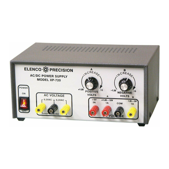
CIRCUIT DESCRIPTION Introduction The Model XP-720 Power Supply features three solid-state DC power supplies and a 12.6VAC center tapped output. The first two supplies consist of one positive and one negative 1.25 to 15 volts at 1 ampere. The third has a fixed 5V at 3 amperes. - Page 16 In practice, the current through the diodes is not as shown in Figure 2C. Because capacitor C5 has a charge after the first cycle, the diode will not conduct until the positive AC voltage exceeds the positive charge in the capacitor. Figure 5 shows a better picture of what the current flow looks like, assuming no loss in the diode.
- Page 17 The LM-317 IC is basically a 1.25V regulator. To be able to vary the output 1.25 - 15V, we stack the IC on a DC voltage as shown in Figure 6A. When LM-317 VR1 equals 0, the output voltage is 1.25V as determined by the LM-317 IC. 1.25 - 15V Note that the voltage across R1 is always 1.25V.
- Page 18 QUIZ 1. AC voltage is supplied to the rectifier stages by the . . . A. step up transformer. B. step down transformer. C. 1 to 1 transformer. D. AC to DC transformer. 2. The secondary windings of the transformer are . . . A.
-
Page 19: Schematic Diagram
SPECIFICATIONS ON XP-720 POWER SUPPLY Input Voltage Current Protection Output Voltage (at 120V input) Output Regulation Line Regulation Ripple Max Current Protection Short Protection Output Impedance Maximum output individually rated. SCHEMATIC DIAGRAM 110-130VAC 1) 1.25-15VDC @ 1A 2) –1.25 - –15VDC @ 1A 3) 5VDC @ 3A 4) 6.3, 12.6CTAC @ 1A 200mV each supply... - Page 20 Elenco ® Electronics, Inc. 150 Carpenter Avenue Wheeling, IL 60090 (847) 541-3800 Web site: www.elenco.com e-mail: elenco@elenco.com...
Need help?
Do you have a question about the XP-720K and is the answer not in the manual?
Questions and answers