
Subscribe to Our Youtube Channel
Related Manuals for Elenco Electronics XP-620K


Summary of Contents for Elenco Electronics XP-620K
- Page 1 POWER SUPPLY KIT MODEL XP-620K Assembly and Instruction Manual Elenco Electronics, Inc. Copyright © 2003, 1989 Elenco Electronics, Inc. Revised 2003 REV-O 75320K...
-
Page 2: Parts List
PARTS LIST If any parts are missing or damaged, see instructor or bookstore. DO NOT contact your place of purchase as they will not be able to help you. Contact Elenco manual) for additional assistance, if needed. Qty. Symbol Value .18W 5% 3W R3, R4 2.7W 5% 1/2W... -
Page 3: Parts Identification
PARTS IDENTIFICATION 2kW W Potentiometer Resistor Capacitor Diode Transistor .18W 3W Resistor Integrated Circuit Transformer PC Board Fuse Switch Heatsink Knob Strain Relief PC Board Stand-off Binding Post Assembly Nuts Mica Fuse Assembly Binding Post 6-32 / 8-32 Flat Washer Lockwashers Lockwasher 5/16”... - Page 4 IDENTIFYING RESISTOR VALUES Use the following information as a guide in properly identifying the value of resistors. BAND 1 1st Digit Color Digit Black Brown Orange Yellow Green Blue Violet Gray White IDENTIFYING CAPACITOR VALUES Capacitors will be identified by their capacitance value in pF (picofarads), nF (nanofarads), or mF (microfarads). Most capacitors will have their actual value printed on them.
-
Page 5: Safety Procedures
CONSTRUCTION Introduction The most important factor in assembling your XP-620K Power Supply Kit is good soldering techniques. Using the proper soldering iron is of prime importance. A small pencil type soldering iron of 25 - 40 watts is recommended. The tip of the iron must be kept clean at all times and well tinned. - Page 6 ASSEMBLE COMPONENTS TO PC BOARD Figure A Band Diodes have polarity. Be sure that the band is in the correct direction. D5 - 1N5400 Diode D6 - 1N5400 Diode D7 - 1N5400 Diode D8 - 1N5400 Diode (see Figure A) C1 - 10mF Electrolytic C2 - 10mF Electrolytic C3 - 10mF Electrolytic...
- Page 7 PC BOARD WIRING Cut the wires to the required length. Strip 1/4” of insulation off of both ends. Insert the lead into the hole and solder it to the foil side. 4” Red Hole K 4” Orange Hole J 3” Red Hole I 3”...
-
Page 8: Panel Assembly
PANEL ASSEMBLY Install the binding posts with the colors in order, as shown in Figure D. Remove the large nut and splitwasher. Insert the post into the hole and fasten it with the nut and splitwasher. Tighten down the nut with pliers. Cut off the tabs on the two potentiometers and install them with the lugs up, as shown in Figure D. - Page 9 Carefully bend the leads of IC1, IC2, IC3 and Q2 at right angles with pliers. Install IC1, IC2 and Q2 in the positions shown in Figure E. Fasten in place using the parts shown in Figure F. Spread the silicon grease on the back of the transistor and ICs.
- Page 10 WIRING LINE CORD, FUSE, TRANSFORMER AND SWITCH Install the line cord ground lug to the chassis using a 6-32 x 3/8” screw and a 6-32 large nut in the location shown in Figure J. Strip the insulation off of both ends of the 6”...
- Page 11 WIRE BINDING POSTS AND 317, 337 Solder the wires from the board to the binding posts, as shown in Figure K. 3” Blue wire from (G) on the PC board; To the Yellow post (–1.5 - 15V). 3” Orange wire from (H) on the PC board; To the Black post (common). 6”...
- Page 12 WIRE 2N6124, 7805 & POTENTIOMETERS Insert the wires from the PC board through the rectangular hole in the chassis to the 2N6124 and LM-7805, solder into place, as shown in Figure L. 5” Red wire (L) from the PC board; To middle lead 0f 2N6124.
-
Page 13: Final Assembly
FINAL ASSEMBLY Fasten the heat sink to the chassis with two 6 x 3/8” black screws, as shown in Figure M. Fit the cover onto the chassis. Fasten in place with two 6 x 3/8” truss head black screws on each side, as shown in Figure M. -
Page 14: Troubleshooting Guide
TROUBLESHOOTING GUIDE No 2 - 15V Output Voltage 1) Check the AC voltage at anode of D1. It should read about 17VAC. If not, check the fuse, transformer, ON/OFF switch or line cord. 2) Measure voltage at output of D1. It should read about 24VDC. If not, check D1, D3 and C5. 3) If 20V is OK, check IC1. -
Page 15: Circuit Description
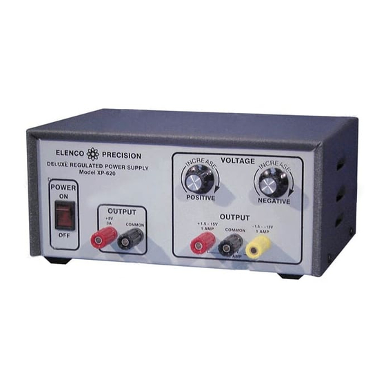
CIRCUIT DESCRIPTION Introduction The Model XP-620 Power Supply features three solid-state DC power supplies. The first supply gives a negative 1.5 to 15 volts at 1 ampere. The third has a fixed 5V at 3 amperes. All DC supplies are fully regulated. A special IC circuit keeps the output voltage within .2V when going from no load to 1 ampere. - Page 16 In practice, the current through the diodes is not as shown in Figure 2C. Because capacitor C5 has a charge after the first cycle, the diode will not conduct until the positive AC voltage exceeds the positive charge in the capacitor.
- Page 17 The LM-317 IC is basically a 2V regulator. To be able to vary the output 2 - 15V, we stack the IC on a DC voltage as shown in Figure 6A. When VR1 equals 0, LM-317 the output voltage is 2V as determined by the LM-317 IC. Note that the voltage 2 - 15V across R1 is always 2 volts.
- Page 18 QUIZ 1. AC voltage is supplied to the rectifier stages by the A. step up transformer. B. step down transformer. C. 1 to 1 transformer. D. AC to DC transformer. 2. The secondary windings of the transformer are . . . A.
-
Page 19: Schematic Diagram
SPECIFICATIONS ON XP-620 POWER SUPPLY Input Voltage Output Voltage (at 120V input) Output Regulation Line Regulation Ripple Max Current Protection Short Protection Output Impedance SCHEMATIC DIAGRAM 110-130VAC 1) 1.5-15VDC @ 1A 2) 1.5-15VDC @ 1A 3) 5VDC @ 3A 200mV each supply 100mV each supply 5mV rms 1A limit 2-15VDC... - Page 20 Elenco Electronics, Inc. 150 W. Carpenter Avenue Wheeling, IL 60090 (847) 541-3800 http://www.elenco.com e-mail: elenco@elenco.com...
Need help?
Do you have a question about the XP-620K and is the answer not in the manual?
Questions and answers