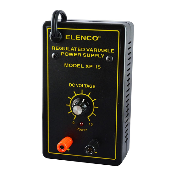
Elenco Electronics XP-15 Instruction & Assembly Manual
Hide thumbs
Also See for XP-15:
- Assembly and instruction manual (13 pages) ,
- Instruction manual (8 pages)
Table of Contents
Advertisement
Quick Links
Advertisement
Table of Contents

Subscribe to Our Youtube Channel
Summary of Contents for Elenco Electronics XP-15
- Page 1 POWER SUPPLY KIT MODEL XP-15K Instruction & Assembly Manual ELENCO ® Copyright © 2012, 1991 by ELENCO ® All rights reserved. Revised 2012 REV-P 753015 No part of this book shall be reproduced by any means; electronic, photocopying, or otherwise without written permission from the publisher.
-
Page 2: Parts List
INTRODUCTION Assembly of your XP-15K Regulated Variable Power Supply Kit will prove to be an exciting project and give much satisfaction and personal achievement. If you have experience in soldering and wiring technique, you should have no problem in the assembly of this kit. Care must be given to identifying the proper components and in good soldering habits. Above all, take your time and follow the easy step-by-step instructions. -
Page 3: Parts Verification
PARTS VERIFICATION Before beginning the assembly process, familiarize yourself with the components and this instruction book. Verify that all of the parts are present. This is best done by checking off the parts in the parts list. RESISTORS CAPACITOR SEMICONDUCTORS Carbon film Diode 2kΩ... - Page 4 CONSTRUCTION Introduction • Turn off iron when not in use or reduce temperature setting when using a soldering station. The most important factor in assembling your XP-15K Regulated Variable Power Supply Kit is good soldering techniques. Using the • Tips should be cleaned frequently to remove oxidation before it becomes proper soldering iron is of prime importance.
- Page 5 MOUNTING THE TRANSFORMER & BINDING POSTS r Peel the backing off of the label and place it onto the case top, while carefully lining up the 6-32 Nut holes as shown in Figure A. The label should fit snug within #6 Lockwasher the indentation in the case.
- Page 6 ASSEMBLE COMPONENTS TO THE PC BOARD Place a check mark in the box provided next to each step to indicate that the step is completed. C4 - 220μF Electrolytic (see Figure D) D4 - 1N4001 Diode D5 - 1N4001 Diode D3 - 1N4001 Diode D6 - 1N4001 Diode D2 - 1N4001 Diode...
- Page 7 WIRING Install the following wires as shown in Figure G. r Cut the blue and both yellow transformer wires so that they are 4”. Strip 1/4” insulation off the ends. Blue wire Yellow wires r Solder one of the yellow wires from the transformer to PC Board P1 and the other to P3.
-
Page 8: Final Assembly
LINE CORD ASSEMBLY FINAL ASSEMBLY Install the following wires as shown in Figure K. r Remove the backing from each rubber foot and r Cut the two black wires from the transformer to place them in the locations shown in Figure L. 1½”. -
Page 9: Circuit Description
TESTING THE XP-15K POWER SUPPLY Testing the XP-15K Power Supply is very simple. Set the output voltage to 15 volts and place a 75Ω 5 Before applying power to the unit, be sure that all of watt resistor across the output terminals. Again, the the wiring and soldering is firm. - Page 10 Each diode conducts when the voltage is positive. depending on the current drawn By adding the two outputs, the voltage presented to by the output load. Remember, capacitor C1 is more complete, thus, easier to filter, current only flows through the as shown in Figure 2F.
-
Page 11: Troubleshooting Guide
TROUBLESHOOTING GUIDE Consult your instructor or contact ELENCO ® if you have any problems. DO NOT contact your place of purchase as they will not be able to help you. LED Not Lit Poor Regulation 1) Check transformer and line cord. 1) Check AC ripple at the input of the regulator. -
Page 12: Schematic Diagram
SCHEMATIC DIAGRAM ELENCO ® 150 Carpenter Avenue • Wheeling, IL 60090 (847) 541-3800 • Website: www.elenco.com • e-mail: elenco@elenco.com...


Need help?
Do you have a question about the XP-15 and is the answer not in the manual?
Questions and answers