Elenco Electronics XP-15K Assembly And Instruction Manual
Power supply kit
Hide thumbs
Also See for XP-15K:
- Assembly and instruction manual (13 pages) ,
- Instruction & assembly manual (13 pages)

Subscribe to Our Youtube Channel
Related Manuals for Elenco Electronics XP-15K


Summary of Contents for Elenco Electronics XP-15K
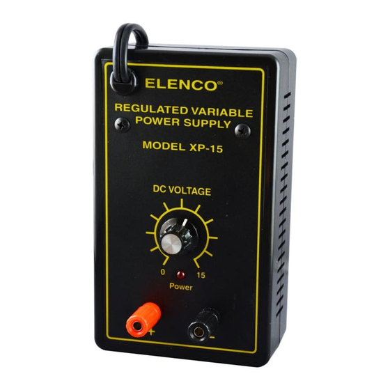
- Page 1 POWER SUPPLY KIT MODEL XP-15K Assembly and Instruction Manual Elenco Electronics, Inc. Copyright © 1991 Elenco Electronics, Inc. Revised 2001 REV-H 753015...
-
Page 2: Parts List
If any parts are missing or damaged, see instructor or bookstore. DO NOT contact your place of purchase as they will not be able to help you. Contact Elenco Electronics (address/phone/e-mail is at the back of this manual) for additional assistance, if needed. -
Page 3: Soldering Techniques
INTRODUCTION Assembly of your XP-15 Regulated Variable Power Supply Kit will prove to be an exciting project and give much satisfaction and personal achievement. If you have experience in soldering and wiring technique, you should have no problem in the assembly of this kit. Care must be given to identifying the proper components and in good soldering habits. -
Page 4: Panel Assembly
PANEL ASSEMBLY Install the potentiometer with the lugs down as shown in Figure A. Remove the tab as shown. Fasten in place with the parts as shown in Figure B. Turn the shafts on the pots fully counter-clockwise. Push the knobs onto the shafts so that the line on the knob lines up with the end of the circle on the front panel as shown. -
Page 5: Component Assembly
COMPONENT ASSEMBLY Note: When you are instructed to “fasten” a lead to a lug, make a connection, but do not solder until later. Install the following components as shown in Figure G. Fasten the banded end of a 1N4001 diode to terminal 1 of the terminal strip. Fasten the other end to terminal 2. - Page 6 WIRING Install the following wires as shown in Figure I. Cut both yellow transformer wire so that they are 3”. Strip 1/4” insulation off the end. Solder one of the yellow wires from the transformer to terminal 3 on the terminal strip (when soldered, there should be one wire and one diode on the terminal).
-
Page 7: Final Assembly
LINE CORD ASSEMBLY Install the following wires as shown in Figure J. Cut the two black wires from the transformer to 1 1/2”. Strip 1/4” of insulation off of each wire. Feed 2 inches of line cord into the hole of the chassis. -
Page 8: Circuit Description
TESTING THE XP-15 POWER SUPPLY Testing the XP-15K Power Supply is very simple. Before applying power to the unit, be sure that all of the wiring and soldering is firm. If so, obtain a digital voltmeter. Apply power to the XP-15K and vary the voltage control knob. - Page 9 The 1N4001 has a peak current rating of 10 amps. REGULATOR CIRCUIT The regulator circuit in the Model XP-15K Power Supply consists of a LM-317 integrated circuit. This IC is specially designed to perform the regulation function.
-
Page 10: Troubleshooting Guide
TROUBLESHOOTING GUIDE Consult your instructor or contact Elenco Electronics if you have any problems. DO NOT contact your place of purchase as they will not be able to help you. LED Not Lit 1) Check transformer and line cord. 2) Check for 20VDC at the cathode of D1. -
Page 11: Schematic Diagram
SCHEMATIC DIAGRAM -10-... - Page 12 Elenco Electronics, Inc. 150 W. Carpenter Avenue Wheeling, IL 60090 (847) 541-3800 http://www.elenco.com e-mail: elenco@elenco.com...
Need help?
Do you have a question about the XP-15K and is the answer not in the manual?
Questions and answers