
Related Manuals for Elenco Electronics ST-3030


Summary of Contents for Elenco Electronics ST-3030
- Page 1 OPERATOR’S INSTRUCTION MANUAL ST-3030 3¾ AC/DC DIGITAL CLAMP METER Copyright © 2008 Elenco ® Electronics, Inc.
-
Page 2: Table Of Contents
1. Safety Information 2. Safety Symbols 3. General Specifications 4. Introduction 5. Features 6. Specifications 7. Display Details 8. Electrical Specifications 9. Operation 10. Battery Replacement 11. Maintenance PLEASE READ THIS INSTRUCTION MANUAL CAREFULLY Misuse and/or abuse of this instruction manual cannot be prevented by any printed word and may cause injury and/or equipment damage. -
Page 3: Safety Information
1. Safety Information To ensure that the meter is used safely, follow all of the safety and operation instructions in this manual. If the meter is not used as described in the manual, the safety features of the meter might be impaired. -
Page 4: Safety Symbols
2. Safety Symbols This marking adjacent to another marking, terminal, or operating device indicates that the operator must refer to the explanation in the operating instructions to avoid damage to the equipment and/or to avoid personal injury. This WARNING sign denotes a hazard. It calls attention to a procedure, practice or the like, which if WARNING not correctly performed or adhered to, could result in... -
Page 5: General Specifications
3. General Specifications Display Range Control Polarity Zero Adjustment Overrange Indication Low Battery Indication Data Hold Relative Measurement Clamp Opening Size Auto Power Off Safety Standards Operating Environment Temperature 32 Storage Environment Power Supply Dimensions Weight 3¾ digit LCD with a max. reading of 4,000 Auto range &... -
Page 6: Introduction
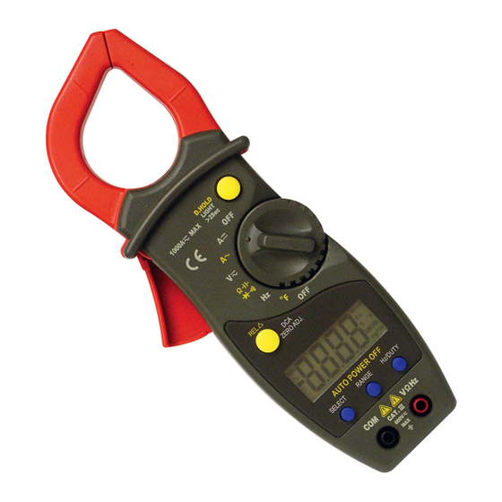
4. Introduction The Elenco ST-3030 is a 3¾ (4,000 count) AC/DC digital clamp ® ammeter and multitester. measurements required by service technicians. AC/DC voltages, AC/DC current and resistance. It also has a diode test function and a continuity beeper. Other features include data hold min/max memory and auto power off. - Page 7 1. Transformer Jaws 2. Barrier - Hand guard holds meter below this barrier. DO NOT touch any bare wires that the clamped around. 3. Data Hold / Light Button - Holds reading in display when the D-Hold button is pressed and released. Also turns on the back light.
-
Page 8: Display Details
7. Display Details The Auto (ranging) annunciator is on when the meter is set to a function that has multiple ranges available. The meter is Auto completely automatic and does not require the user to select a range. The AC ~ annunciator is on when the meter is set to measure AC voltage or current. - Page 9 Fahrenheit Annunciator - This annunciator is displayed whenever the Temperature measurement mode is selected for Fahrenheit display. Centrigrade Annunciator - This annunciator is displayed whenever the Temperature measurement mode is selected for Centrigrade display. Ω Resistance (Ohms) Annunciators - These annunciators are displayed whenever Resistance is being measured.
-
Page 10: Electrical Specifications
8. Electrical Specifications Accuracies are ±(% of reading + number in last digit) at 29 ±5 DC Voltage Range 400mV 400V 600V Overload Protection: 600VDC or AC rms Impedance: 10MΩ. More than 100MΩ on 400mV range AC Voltage Range 400mV 400V 600V The 400mV range can be selected by pressing the “RANGE”... - Page 11 Resistance Range 400Ω 4kΩ 40kΩ 400kΩ 4MΩ 40MΩ Overload Protection: 250VDC or AC rms Capacitance Range 40nF 400nF 4μF 40μF 100μF Overload Protection: 250VDC or AC rms Diode and Audible Continuity Test Range Description Display read approximately forward voltage of diode Built-in buzzer sounds if resistance is less than 120Ω...
-
Page 12: Operation
Duty Cycle 0.1%~99.9%: ±(2.0% +2) Frequency lower than 10kHz Sensitivity: sine wave 0.6V rms Overload Protection: 200VDC or AC rms Temperature Range –4~302 302~1472 NiCr-NiSi sensor Overload Protection: 250VDC or AC rms 9. Operation DC and AC Voltage Measurement 1. Connect the black test lead to the “COM” socket and the red test lead to the “VΩHz”... -
Page 13: Ac Current Measurement
AC Current Measurement 1. Set the selector switch to the desired “A 2. Disconnect the test leads from the meter. 3. Clamp the jaws around the one conductor to be measured. Center the conductor within the jaw using the centering marks as guides. -
Page 14: Diode And Audible Continuity Test
Diode and Audible Continuity Test 1. Connect the black test lead to “COM” socket and the red test lead to the “VΩHz” socket. 2. Set the selector switch to desired “Ω 3. Press the “SELECT” button to choose either a diode or audible continuity measurement. -
Page 15: Relative Measurement
Back Light On any range, press the “D.HOLD” button for over two seconds to light the backlight. Press it again for more than two seconds to wink the light. Relative Measurement Press the “REL ” button. You can measure the relative value and the “... -
Page 16: Battery Replacement
10. Battery Replacement 1. When the battery voltage drops below the proper operating range, the “ ” (low battery) symbol will appear on the LCD display. 2. Before changing the battery, set the selector switch to the “OFF” position. Open the battery compartment cover with a phillips screwdriver.
Need help?
Do you have a question about the ST-3030 and is the answer not in the manual?
Questions and answers