Table of Contents
Advertisement
Quick Links
藍色線條為尺寸標示,請勿印刷上去!
© 2019 Thermaltake Technology Co., Ltd. All Rights Reserved. A-2019.09
All other registered trademarks belong to their respective companies.
Questo manuale d'istruzione è fornito da trovaprezzi.it. Scopri tutte le offerte per
ARGB
o cerca il tuo prodotto tra le
125 mm
www.thermaltake.com
migliori offerte di Case e Alimentatori
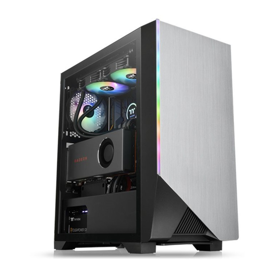
Picture is for reference only
Thermaltake H550 TG
User's Manual
Benutzerhandbuch
Mode d'emploi
Manual del usuario
Manuale dell'utente
Manual do Utilizador
安裝說明書
用戶手冊
ユーザーズマニュアル
Руководство пользователя
kullanıcı elkitabı
(EEE Yönetmeliğine Uygundur)
คู ่ ม ื อ การใช้
Advertisement
Table of Contents

Related Manuals for Thermaltake H550 TG ARGB


Summary of Contents for Thermaltake H550 TG ARGB
- Page 1 Manual del usuario Manuale dell’utente Manual do Utilizador 安裝說明書 用戶手冊 ユーザーズマニュアル © 2019 Thermaltake Technology Co., Ltd. All Rights Reserved. A-2019.09 Руководство пользователя All other registered trademarks belong to their respective companies. www.thermaltake.com kullanıcı elkitabı (EEE Yönetmeliğine Uygundur) คู ่ ม ื อ การใช้...
-
Page 2: Table Of Contents
Radiator Installation Chapter 3. Leads Installation Case LED Connection USB 3.0 Connection Audio Connection Chapter 4. Other Thermaltake Power Supply Series (Optional) Tt RGB Plus Ecosystem *Picture for reference only *Information in the user manual is subject to change without notice... - Page 3 Model H550 TG ARGB Figure Parts Name Q’ty Used for Case Type Middle tower Screw M3 x 5mm Motherboard / 2.5" SSD Dimension (H*W*D) 441 x 225 x 472 mm (17.36 x 8.85 x 18.58 inch) Screw #6-32 x 5mm 3.5"...
-
Page 4: Warning And Notice
Warning and Notice CPU Cooler Height Limitation VGA ( Add- on card) Length Limitation Atenção!! - Limite de altura para o dissipador do CPU: O limite de altura para o dissipador do CPU é 165 mm ( polegadas). - Limite de comprimento para VGA (placa gráfica): <165 mm O limite de comprimento para VGA (placa gráfica) é... -
Page 5: Side Panel Disassembly
PSU Installation Side Panel Disassembly English / 繁體中文 / Place the power supply in proper location and 將電源供應器放在正確的位置,並用螺絲固定 English / 繁體中文 / secure it with screws. 鎖上。 Remove the screws on the back of the chassis, 移除機殼後方螺絲,將側窗打開。 and open the side panel. Deutsch / 简体中文... -
Page 6: Motherboard Installation
3.5” & 2.5" HDD Installation Motherboard Installation English / 繁體中文 / 1.Lay down the chassis. 1. 將機殼平放。 2.Install the motherboard in proper location and 2. 將主機板放置在合適的位置並用零件包中之螺 secure it with screws. 絲固定。 Deutsch / 简体中文 / 1.Legen Sie das Gehäuse auf die Seite. 1. - Page 7 PCI Card Installation PCI Card Installation Type A Traditional GPU instalation Type B (Optional) Vertical GPU installaion English / 繁體中文 / 1. Loosen the screws with a screwdriver. 1. 用螺絲起子將螺絲取下. 2. Install the PCI card in proper location and secure 2.
-
Page 8: Rgb Switch Mode
RGB Switch Mode Note: I/O Port Mode 1 Wave Mode Mode 2 Flow Mode Mode 3 (Single Color) RGB Lighting Radar Mode Mode 4~10 (Red, Yellow, Green, Cyan, Blue, White, Purple) Mode 11~18 Breath Mode (RGB, Red, Yellow, Green, Cyan, Blue, White, Purple) Mode 19 Full Lighted Mode Mode 20~26... -
Page 9: Air Cooling Installation
Air Cooling Installation Radiator Installation ※The radiator is applicable up to 40 mm high Back Back 120 mm x 2 240 mm x 1 120 mm x 1 120 mm x 1 140 mm x 2 Front 140 mm x 1 360 mm x 1 Front 140 mm x 2... -
Page 10: Chapter 3. Leads Installation
Leads Installation Français English Guide d'installation des fils Leads Installation Guide A. Connexion des voyants du boîtier / Sur la face avant du boîtier, vous trouverez plusieurs voyants et les fils des Case LED Connection / On the front of the case, you can find some LEDs and switch leads. Please consult your boutons. - Page 11 Italiano 繁體中文 線材安裝說明 Guida di installazione dei contatti A. 機殼LED連接方式 / 在機殼前方的面板後面,可以找到一些LED與開關線材(POWER Switch….),請參考主機板使用說明 Connessione del LED del case / Nella parte anteriore del case, sono presenti alcuni contatti per interruttori e LED. 書,並將機殼上的線材正確地連接到主機板上,這些線材通常都會印有標籤在上面,如果沒有的話,請找出機殼前方面板上線 Consultare il manuale utente del produttore della scheda madre, quindi connettere i contatti alla parte superiore del 材原本的位置以知道正確的來源。...
- Page 12 日本語 Türkçe リード線の取り付けガイド Ara Kablo Kurulum Kılavuzu Kasa ışık bağlantısı / Kasanın ön kısmında bazı ışıklar ve anahtar ara kabloları görebilirsiniz. Lütfen anakart üreticinizin ケース LED の接続 / ケース前面には、LEDとスイッチリード線があります。 マザーボードメーカーのユーザーマニュ sağladığı kullanım kılavuzuna bakın ve daha sonra, bu ara kabloları, anakart üzerindeki panel bağlantı noktalarına bağlayın. アルを参照し、これらのリード線をマザーボードのパネルヘッダに接続してください。...
- Page 14 Note:...
Need help?
Do you have a question about the H550 TG ARGB and is the answer not in the manual?
Questions and answers