Viessmann Vitoplex 100 Installation Instructions For Contractors
Oil/gas boiler
Hide thumbs
Also See for Vitoplex 100:
- Service instructions for contractors (33 pages) ,
- Service instructions manual (33 pages) ,
- Service instructions manual (32 pages)

Subscribe to Our Youtube Channel
Related Manuals for Viessmann Vitoplex 100


Summary of Contents for Viessmann Vitoplex 100
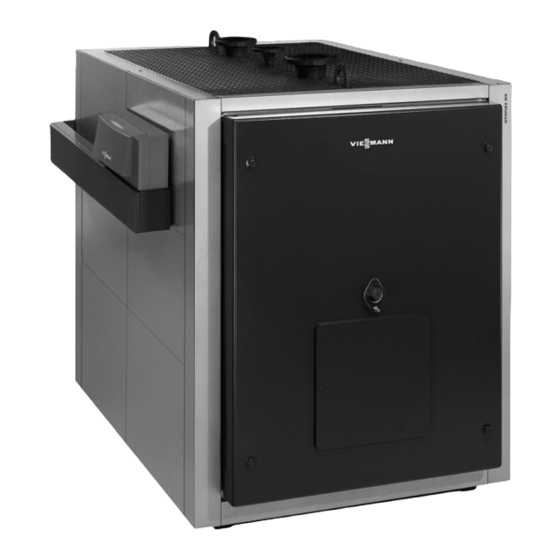
- Page 1 VIESMANN Installation instructions for contractors Vitoplex 100 Type PV1B 780 to 2000 kW 08 to 13 Oil/gas boiler VITOPLEX 100 Dispose after installation. 5461415 GB 9/2018...
- Page 2 Safety instructions Please follow these safety instructions closely to prevent accidents and material losses. Safety instructions explained Danger Note This symbol warns against the risk of injury. Details identified by the word "Note" contain additional information. Please note This symbol warns against the risk of material losses and environmental pollution.
-
Page 3: Table Of Contents
Index Information Disposal of packaging ................Symbols ....................Intended use ..................Product information ................System examples .................. Preparing for installation Clearance dimensions ................Thermal insulation components ............. Thermal insulation pack, part 1 ............■ Thermal insulation pack, part 2 ............■... -
Page 4: Information Disposal Of Packaging
Please dispose of packaging waste in line with statu- DE: Use the disposal system organised by tory regulations. Viessmann. AT: Use the ARA statutory disposal system (Altstoff Recycling Austria AG, licence number 5766). CH: Packaging waste is disposed of by the HVAC contractor. -
Page 5: Product Information
Intended use also includes the adherence to mainte- nance and inspection intervals. Product information Vitoplex 100, type PV1B ■ Fuels: Fuel oil and natural gas Permissible operating pressure 6 bar (0.6 MPa) ■... -
Page 6: Preparing For Installation Clearance Dimensions
Clearance dimensions Dimensions in brackets are minimum clearances. 200 (100) 500 (50) (300) 500 (50) Fig. 1 Fig. 2 Boiler Burner Anti-vibration boiler supports (accessories) Rated heating output 1120 1350 1700 2000 1650 2150 2400 Observe the installed burner length Anti-vibration boiler supports Permissible load 3000... -
Page 7: Thermal Insulation Pack, Part 1
Thermal insulation components (cont.) Thermal insulation pack, part 1 Fig. 3 Front panel, bottom Thermal insulation mat, back bottom Front panel, top Back panel, top Side panel Back panel, bottom Side panel, top, 3 x Side panel, control unit Thermal insulation jacket Thermal insulation jacket, centre... -
Page 8: Thermal Insulation Pack, Part 2
Thermal insulation components (cont.) Thermal insulation pack, part 2 Fig. 4 Side panel Mounting bracket fascia Corner rail Cable trunking, lower section Fixing rail, right front, left back Trunking retainer Fixing rail, left front, right back Cable trunking, upper section Centre rail Fixings: Corner rail, front right with logo... -
Page 9: Installation Sequence Siting And Levelling The Boiler
Siting and levelling the boiler Fig. 5 Level the boiler horizontally. No special foundations Note are required. We recommend installing the boiler on anti-vibration boiler supports (see page 6). Note In order to load the spring elements evenly, floor undu- Adjustable feet or adjustable screws with locking nuts lations should not be more prominent than 1 mm. -
Page 10: Changing The Boiler Door Opening
Changing the boiler door opening Fig. 6 By resetting bolts the door can be hinged on the During installation observe the following: right. Sealing frame should press centrally onto boiler door gasket when the boiler door is closed. Align Danger mounting bracket if required. -
Page 11: Closing Off The Sight Glass Aperture On Burners Without Ventilation Connection
Combustion chamber sight glass (cont.) Fig. 7 2. Only for burners with ventilation connection: Connect plastic hose with the sight glass and the fan part of the burner (test port for "static burner pressure"). Closing off the sight glass aperture on burners without ventilation connection On burners without ventilation connection for sight glass, the sight glass aperture in the boiler door is closed off with a plug. - Page 12 Combustion chamber sight glass (cont.) 2. Apply adhesive all around the plug. Insert plug. Note Adhesive drying time: 24 hours Fig. 9...
-
Page 13: Connections On The Heating Water Side
Connections on the heating water side Note Install all pipe connections free of load and torque stress. Fig. 10 Boiler return Boiler flow 780 and 950 kW: DN 100 780 and 950 kW: DN 100 1120 and 1350 kW: DN 125 1120 and 1350 kW: DN 125 1700 and 2000 kW: DN 150 1700 and 2000 kW: DN 150... -
Page 14: Fitting The Thermal Insulation
Fitting the thermal insulation Boiler body thermal insulation Parts required from thermal insulation pack 1 Parts required from thermal insulation pack 2 Thermal insulation jacket Thermal insulation mat, top back Thermal insulation mat, bottom back Spring hooks from bag of fixing parts Fig. - Page 15 Fitting the thermal insulation (cont.) 2 - 3 Fig. 12 Top rail Base rail Bag with type plate 1. Remove bag containing the type plate and keep 2. Thread the wing nuts and washer into the top and safe. This will be required later. base rails without tightening them.
- Page 16 Fitting the thermal insulation (cont.) Fig. 13 Aligning the fixing rails 2. Align the fixing rails and tighten with the wing nuts. 1. Provisionally hook the side panels into position. To 3. Remove the side panels again. provide better alignment it may be necessary to also hook in the corner rails (see the following page).
-
Page 17: Mounting The Corner Rails
Fitting the thermal insulation (cont.) Mounting the corner rails Parts required from thermal insulation pack 2 Corner rails Fig. 14 1. Clip 2 spring clips into each corner rail. 3. Secure the corner rails with 3 screws each. 2. Hook corner rails into the fixing rails. Align corner rails vertically and horizontally. -
Page 18: Control Unit Mounting Bracket, Control Unit Back Panel And Burner Cables
Mounting the control unit (cont.) Edge protector Mounting bracket Control unit mounting bracket, control unit back panel and burner cables Fig. 15 Prior to mounting the side panels, route the burner Note cable and the boiler water temperature sensor lead. If no burner cables were supplied, provide burner The side panel for the control unit can be mounted on cables on site. - Page 19 Mounting the control unit (cont.) B4.8 x 9.5 B4.8 x 9.5 Fig. 16 Mounting the control unit 2 screws are supplied to secure the control unit. Fig. 17 Please note Damaged capillaries result in temperature sensor faults. Never kink the capillary tubes.
-
Page 20: Cable Trunking
Mounting the control unit (cont.) Cable trunking Parts required from thermal insulation pack 2 Cable trunking, upper section Mounting bracket fascia Trunking retainer Cable trunking, lower section Fig. 18 Note on step 5. After the cables/leads have been connected, secure mounting bracket fascia to the mounting bracket. -
Page 21: Front Panels
Mounting panels (cont.) Front panels Fig. 19 Back panels Fig. 20 Hook back panels into the slots provided. -
Page 22: Boiler Coding Card And Type Plate
Mounting panels (cont.) Boiler coding card and type plate Fig. 21 Type plate Coding card Connections on the flue gas side 2x Ø D Ø 10 mm Ø D Fig. 22... -
Page 23: Mounting The Burner
Connections on the flue gas side (cont.) 1. Connect the flue outlet with the shortest possible 2. Create a test port. run to the chimney and maintain a slight incline. The version of flue gas collector and cleaning 3. Insulate the flue pipe. cover depends on the output rating. -
Page 24: Pressure Switch
Mounting the burner (cont.) Burner weight subject to centre of gravity 0.40 0.60 0.80 1.00 1.20 1.40 1.60 1.80 2.00 Distance of boiler centre of gravity to the boiler door in m Fig. 24 PV1B 1350 to 2000 kW PV1B 780 to 1120 kW Example for rated heating output 1350 kW: 2. -
Page 25: Commissioning And Adjustment
Commissioning and adjustment Service instructions for boiler and boiler control unit plus separate burner documentation... - Page 28 Viessmann Werke GmbH & Co. KG Viessmann Limited D-35107 Allendorf Hortonwood 30, Telford Telephone: +49 6452 70-0 Shropshire, TF1 7YP, GB Fax: +49 6452 70-2780 Telephone: +44 1952 675000 www.viessmann.com Fax: +44 1952 675040 E-mail: info-uk@viessmann.com...
Need help?
Do you have a question about the Vitoplex 100 and is the answer not in the manual?
Questions and answers