Table of Contents
Advertisement
Quick Links
Advertisement
Table of Contents

Related Manuals for Tach-It TWISTERS 3567


Summary of Contents for Tach-It TWISTERS 3567
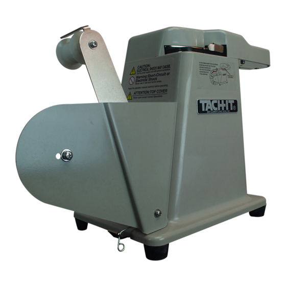
- Page 1 TACH-IT MODEL #3567 SEMI-AUTOMATIC TWIST TIE MACHINE REPAIR MANUAL 01/05...
-
Page 2: Table Of Contents
TABLE OF CONTENTS: SECTION 1—REMOVING AND REPLACING TOP COVER: PAGE 3 SECTION 2—REPLACING THE CUTTER BLADES: PAGE 4 SECTION 3—REMOVING AND REPLACING THE SEGMENT PAGES 5-6 GEAR: SECTION 4—REMOVING AND REPLCING OF UPPER PLATE: PAGES 7-9 PAGE 10 SECTION 5—REPLACING THE TWISTER ASSEMBLY AND TWISTER GEAR: SECTION 6—REMOVING AND REPLACING THE TWISTING PAGES 11-12... - Page 3 SECTION 1—REMOVING AND REPLACING THE TOP COVER: To remove the Top Cover: Power Cord must be unplugged from electrical outlet prior to removing the Top Cover. 1) Loosen the screw marked below in Figure 1. 2) This machine is equipped with a Safety Interlock. To disengage the Safety Interlock lift the Top Cover straight up.
-
Page 4: Section 2-Replacing The Cutter Blades
SECTION 2—REPLACING THE CUTTER BLADES: 1) Remove the Top Cover as per the instructions in Section 1. 2) Locate the Cutter Blade Linkage. See Figure 4 3) Locate and remove the Cutter Blade Linkage Spring from its post. See Figure 4. 4) Locate the Movable Blade Holding Spring holding the Movable Blade in position. -
Page 5: Section 3-Removing And Replacing The Segment Gear
SECTION 3—REMOVING AND REPLACING THE SEGMENT GEAR: To remove the Segment Gear and Feeding Roller: 1) Unplug the power cord from the electrical outlet. 2) Remove the Top Cover as per instructions in Section 1. 3) Locate the Upper Holding Plate and the 3 Screws Securing it. Remove the 3 Screws and lift the Upper Holding Plate off. - Page 6 SECTION 3—REMOVING AND REPLACING THE SEGMENT GEAR CONTINUED: Remove Screw. Upper Holding Plate Spacer Collar located directly beneath. Remove Screw. Upper Holding Plate Spacer Collar located directly beneath. Remove Screw. Upper Holding Plate Spacer Collar located directly beneath. Figure 7 Upper Holding Plate Figure 8 Switch Lever Spring...
-
Page 7: Section 4-Removing And Replcing Of Upper Plate
SECTION 4—REMOVING AND REPLACING OF UPPER PLATE: Removal of this part is necessary to; change the Twister Assembly, clean debris from under the Upper Plate, change the Needle Left and Needle Right, change the Needle Guard Arm Spring, change the Needle Guard Arm, and to do any other service required on parts located between the Upper Plate and Middle Plate. - Page 8 SECTION 4—REMOVING AND REPLACING OF UPPER PLATE CONTINUED: Figure 9 Tie Feeding Roller and Bushing Tie Feeding Roller Arm Micro-Switch Arm Spring Switch Lock Lever Spring Assembly Ground Wire and Screw Remove screw Figure 10 Remove screw Remove screw Remove screw Hole for Wires Remove screw Remove screw...
- Page 9 SECTION 4—REMOVING AND REPLACING OF UPPER PLATE CONTINUED: To replace the Upper Plate: 1) Hold the Upper Plate over the Middle Plate and insert the 3 wires into the hole from which they were removed. See Figure 10 on previous page. 2) Begin lowering the Upper Plate onto the Middle Plate.
-
Page 10: Section 5-Replacing The Twister Assembly And Twister Gear
SECTION 5—REPLACING THE TWISTER ASSEMBLY AND TWISTER GEAR: 1) Follow the instructions in Section 4 to remove the Upper Plate. 2) Remove the Twister Assembly from the Middle Plate. See Figure 12. 3) Slide the Bushing off the end of the Twister Gear. See Figure 11. 4) Using a 2mm Allen Wrench loosen the set screw on the Twister Gear. -
Page 11: Section 6-Removing And Replacing The Twisting
SECTION 6—REMOVING AND REPLACING THE TWISTING HEAD ASSEMBLY FROM THE BASE OF THE MACHINE: It is necessary to remove the Twisting Head Assembly from the base of the machine if any service is required between the Middle Plate and the Bottom Plate. It may also be required for lubrication or if any work is required on the motor. - Page 12 SECTION 6—REMOVING AND REPLACING THE TWISTING HEAD ASSEMBLY FROM THE BASE OF THE MACHINE CONTINUED: Figure 13 Remove screw Remove screw Remove screw TIE FEEDING ROLLER ARM AND TIE FEEDING ROLLER WITH BUSHING HAVE BEEN RE- MOVED IN ABOVE FIGURE.
-
Page 13: Machine
SECTION 7—REMOVING AND REPLACING OF BOTTOM PLATE: The following parts can be accessed by removing the Bottom Plate; the Needle Cam and the Needle Arm, Needle Left, Needle Right, and the Movable Blade. It may also be necessary to remove the Bottom Plate to lubricate using a medium weight machine grease the Needle Arm and the Needle Cam. - Page 14 SECTION 7—REMOVING AND REPLACING OF BOTTOM PLATE CONTINUED: Remove screw Figure 14 Remove screw Remove screw Remove screw Main Shaft Gear Remove screw Figure 15 Movable Blade Needle Cam Needle Arm Main Shaft...
-
Page 15: Section 8-Lubricating The Needle Arm And Needle Cam
SECTION 8—LUBRICATING THE NEEDLE ARM AND NEEDLE CAM: Lubricating of the Needle Arm and the Needle Cam may be necessary after extended use. Friction between the Needle Arm and the Middle Plate may build up and the symptom of this is that the machine occasionally will not complete a cycle. -
Page 16: Section 9-Replacing Of The Motor, Capacitor
SECTION 9—REPLACING OF THE MOTOR, CAPACITOR, SAFETY INTERLOCK, ON/OFF SWITCH AND FUSE HOLDER To replace the Motor, Capacitor, Safety Interlock, On/Off Switch and Fuse Holder, the Motor Box must be opened. Follow the instructions below on how to Open the Motor Box. There is a sub-section for the replacement of each of the parts previously mentioned. - Page 17 SECTION 9—REPLACING OF THE MOTOR, CAPACITOR, SAFETY INTERLOCK, ON/OFF SWITCH AND FUSE HOLDER CONTINUED: To Change the On/Off Switch: 1) Follow the directions above to open the Motor Box. 2) Pressing the tabs on the On/Off Switch pull forward and remove it from the case. 3) With the new On/Off Switch near, transfer the wires from the old switch to the new switch making sure they are installed in the same place.
- Page 18 SECTION 9—REPLACING OF THE MOTOR, CAPACITOR, SAFETY INTERLOCK, ON/OFF SWITCH AND FUSE HOLDER CONTINUED: Figure 18 Remove screw Remove screw Remove screw Remove screw Figure 19 Fuse Holder On/Off Switch Safety Interlock Not visible, Motor Located within well. Capacitor Perforated Plate See Figure 20 on the next page.
- Page 19 SECTION 9—REPLACING OF THE MOTOR, CAPACITOR, SAFETY INTERLOCK, ON/OFF SWITCH AND FUSE HOLDER CONTINUED: Figure 20 Motor Screw Safety Interlock Screw Safety Interlock Screw Motor Screw Motor Screw Motor Screw...
-
Page 20: Section 10-Maintenance
SECTION 10—MAINTENANCE: The Tach-It Model #3567 has been designed to require as little normally scheduled maintenance as possible. Excess lubrication in this machine becomes a detriment, not a benefit for the machine. In Especially dusty environments, the lubricants attract the dust and become pasty losing any benefit they may have had. - Page 21 SECTION 10—MAINTENANCE CONTINUED: C-Clip Figure 21 Tying Aperture C-Clip located under Switch Lever Spring Rollers and washers Located below the C-Clips. Switch Lever Spring Switching Arm Segment Gear Lubricate this protrusion with medium weight machine grease. Micro-Switch...
-
Page 22: Section 11-Troubleshooting
SECTION 11—TROUBLESHOOTING: PROBLEM CAUSE REMEDY Machine does not operate even Power Cord is not plugged in Plug the Machine into the proper though the On/Off Switch id in Check Fuse Power Outlet the On position (Switch is not Change Fuse if blown 2 amp lit) Machine does not operate even Make sure the Top Cover is on...
Need help?
Do you have a question about the TWISTERS 3567 and is the answer not in the manual?
Questions and answers