
Subscribe to Our Youtube Channel
Related Manuals for SAF SAFphire


Summary of Contents for SAF SAFphire
- Page 1 Installation & Operating Procedures PROGRAMMABLE LINER CONTROLLER HARDWARE GUIDE MANUAL VER. 2.8...
- Page 2 SAFphire Programmable Linear Controller Hardware Guide Manual Version 2.8 06/05/13...
- Page 3 SAFphire Hardware Guide Page 2...
- Page 4 All instructions should be strictly adhered to. The user should consult SAF or a SAF supplier for clarification of the contents of this manual should any doubt or questions arise.
- Page 5 SAFphire Hardware Guide Page 4...
-
Page 6: Table Of Contents
SAFphire Hardware Guide Table of Contents SAFphire Input/Output Cards SAFphire Input/Output Cards ..............5 CA401 DIGITAL INPUT CARD ..............11 MODELS ....................11 JUMPERS and SWITCHES ..............11 TERMINALS .................... 12 LEDS ....................... 12 SPECIFICATIONS ................... 12 CA402 DIGITAL OUTPUT CARD ..............14 MODELS .................... - Page 7 SAFphire Hardware Guide LEDS ....................... 25 SPECIFICATIONS ................... 26 CA407 DRIVE INTERFACE / ENCODER CARD ........... 27 JUMPERS and SWITCHES ..............27 TERMINALS .................... 28 LEDS ....................... 29 POTENTIOMETERS ................29 SPECIFICATIONS ................... 29 CA408 MULTIPROCESSOR CARD .............. 30 JUMPERS and SWITCHES ..............30 TERMINALS ....................
- Page 8 CA413 SCANPORT INTERFACE CARD ............46 JUMPERS and SWITCHES ..............46 TERMINALS .................... 46 LEDS ....................... 46 SPECIFICATIONS ................... 47 CA414 SAF-LINK COMMUNICATIONS GATEWAY ........48 JUMPERS and SWITCHES ..............48 TERMINALS .................... 49 LEDS ....................... 49 CHANGING THE BATTERY ..............49 SPECIFICATIONS ...................
- Page 9 SAFphire Hardware Guide SPECIFICATIONS ................... 59 CA419 DDCS INTERFACE CARD ..............60 JUMPERS and SWITCHES ..............60 TERMINALS .................... 60 LEDS ....................... 60 SPECIFICATIONS ................... 60 CA451 MULTIPROCESSOR CARD .............. 61 JUMPERS and SWITCHES ..............61 TERMINALS .................... 63 LEDS ....................... 64 SPECIFICATIONS ...................
- Page 10 SAFphire Hardware Guide BITBUS INTERFACE CARD ................77 REQUIREMENTS ..................77 HARDWARE INSTALLATION ..............77 JUMPER SETTINGS ................77 RS232 TO BITBUS CONVERTOR ..............79 LEDs ......................79 CA406 DOWNLOAD CARD ................80 JUMPERS and SWITCHES ..............80 TERMINALS .................... 81 LEDS .......................
- Page 11 SAFphire Hardware Guide SYSTEM MAINTENANCE ................95 CA408 PROCESSOR CARD ..............95 CA414 SAF-Link CARD & CA408-1 PROCESSOR CARD ....95 TECHNICAL SUPPORT ................. 96 CONTACT US ..................96 Page 10...
-
Page 12: Ca401 Digital Input Card
SAFphire Hardware Guide CA401 Digital Input Card The CA401 is a 16 channel digital input card. The inputs may be 24 VDC or 120 VAC depending on the model of the card. The 16 inputs are made up of two groups of 8 inputs. Each group has its own neutral. -
Page 13: Terminals
THRESHOLD VOLTAGE for the model of card being used. The SAF BUS STATUS LED will be flashing once per second when the card is being accessed by the SAFphire processor card. This LED will not change states when the card is not being accessed. - Page 14 SAFphire Hardware Guide MODEL B (24 VDC inputs) Maximum Input 30 VDC Voltage Input Threshold 12 VDC Voltage Input Current 2 mA Input Filter Delay .1 msec Isolation optical 1.5 kV MODEL D (120 VAC inputs) Maximum Input 140 VAC 50/60...
-
Page 15: Ca402 Digital Output Card
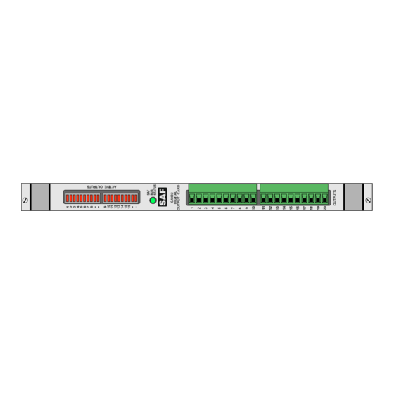
SAFphire Hardware Guide CA402 Digital Output Card The CA402 is a 16 channel digital output card. The outputs are rated at 24 VDC or 120 VAC depending on the model of the card. The 16 outputs are made up of two groups of 8 outputs. Each group has its own output voltage source. -
Page 16: Terminals
The LEDs labeled 1 to 16 will be ON when the corresponding output is The SAF BUS STATUS LED will be flashing once per second when the card is being accessed by the SAFphire processor card. This LED will not change states when the card is not being accessed. -
Page 17: Specifications
SAFphire Hardware Guide SPECIFICATIONS MODEL B (24 VDC Outputs) Maximum Output 100 mA Current Maximum Output 200 V RMS Voltage Minimum Output Voltage Frequency Isolation optical 2.5 kV MODEL D (120 VAC Outputs) Maximum Output 300 mA RMS 5 A peak... -
Page 18: Ca403 Multiple I/O Card
SAFphire Hardware Guide CA403 Multiple I/O Card The CA403 is a multiple input / output card with 3 12 bit bipolar analog inputs, 4 digital inputs, 2 12 bit bipolar analog outputs, 2 digital form C relay outputs and 1 +10 Volt fixed output. The digital inputs may be 24 VDC or 120 VAC depending on the model of the card. -
Page 19: Terminals
SAFphire Hardware Guide TERMINALS Analog Input 1 Common Analog Input 2 Common Analog Input 3 Common Analog Output 1 Common Analog Output 2 Common +10 V Reference Common Logical Output 1 Toggle Logical Output 1 Normally Closed Logical Output 1 Normally... -
Page 20: Potentiometers
SAFphire Hardware Guide POTENTIOMETERS RV1 - RV10 These pots are factory calibrated and should not need user adjustment SPECIFICATIONS Model B Digital Inputs Maximum Input Voltage 30 VDC Input Threshold Voltage 12 VDC Input Current 2 mA Input Filter Delay... - Page 21 SAFphire Hardware Guide Current Draw per Card (both Models) 5 VDC 100 mA +15 VDC 200 mA -15 VDC 200 mA Page 20...
-
Page 22: Ca404 Analog Output Card
SAFphire Hardware Guide CA404 Analog Output Card The CA404 is a four channel, 12 bit, bipolar, non isolated analog output card. JUMPERS and SWITCHES SB1 CARD ADDRESS The address of the CA404 is determined by four dip switches of SB1 labeled A0, A1, A2, A3. -
Page 23: Leds
SAFphire Hardware Guide LEDS The SAF BUS STATUS LED will be flashing once per second when the card is being accessed by the SAFphire processor card. This LED will not change state when the card is not being accessed. POTENTIOMETERS... -
Page 24: Ca406 Serial Interface Card
SB3 - CARD ADDRESS This is the address used by the SAFphire processor card. The address of the CA406 is determined by 3 dip switches of SB3 labeled A0 - A2. The three switches labeled A1 - A4 form an three bit binary address with a valid range of 0 to 7 ( the rest perform other functions on the card.) A0 is... -
Page 25: Terminals
SAFphire Hardware Guide SB3 - ELECTRICAL CHARACTERISTICS The electrical characteristics of the two serial ports on board the CA406 card are determined by 4 dip switches of SB3. The switch labeled MODE1 and the upper of the two switches labeled RS232 (#5) affect serial port1. -
Page 26: Leds
The green LED #4 will be flashing once per second when the Intel 8044 communications processor is operating properly. This LED not flashing indicates a fault condition. LED #1 - LED #3 will count in a binary pattern when the card is being accessed by the SAFphire processor card. Page 25... -
Page 27: Specifications
SAFphire Hardware Guide SPECIFICATIONS Communication Ports BITBUS Baud 375 KBaud Rate Maximum Serial (software configurable) Port Baud Rate 19200 baud Current Draw per Card 5 VDC 520 mA +15 VDC 0 mA -15 VDC 0 mA Page 26... -
Page 28: Ca407 Drive Interface / Encoder Card
The drive interface transfers fault, sequencing, and feedback/reference information between the drive and SAFphire. The analog output used for the current reference in the drive interface is also made available at the output terminals for use with other devices. -
Page 29: Terminals
SAFphire Hardware Guide In the "DIFF" position Signal B is compared to Signal NOT_B to determine the state of channel B. In the "SINGLE" position, Signal B is compared to a voltage which is one half of the PS signal at terminals 1 and 10. Note that in the "SINGLE"... -
Page 30: Leds
(max. length 50 feet). LEDS The SAF BUS STATUS LED will be flashing once per second when the card is being accessed by the SAFphire processor card and the DRIVE_ENABLE parameter of the CA407_OUTPUT block is ON. This LED will not change states when the card is not being accessed or if the DRIVE_ENABLE parameter of the CA407_OUTPUT block is OFF. -
Page 31: Ca408 Multiprocessor Card
SAFphire Hardware Guide CA408 Multiprocessor Card The CA408 card is a high speed processor card which executes block programs that are created on a personal computer using an SBL editor package. The CA408 will accept inputs and update outputs of the cards in the same physical rack as controlled by the block program downloaded to it. -
Page 32: Terminals
SAFphire Hardware Guide JP 1 Normal operation is in "BC" position. JP 2 Normal operation is in the "DE" position. JP 3 Normal operation is in the "AEAF" position. JP 4 Normal operation is in the "HI" position. JP 5 Normal operation is in the ABAC position. -
Page 33: Leds
SAFphire Hardware Guide LEDS The red POWER LED will be ON when the +5 VDC power supply is present. The green 8044 STATUS LED will be flashing once per second when the Intel 8044 communications processor is operating properly. This LED not flashing indicates a fault condition. -
Page 34: Ca408-1 Multiprocessor Card
SAFphire Hardware Guide CA408-1 Multiprocessor Card The CA408-1 card is a high speed processor card which executes block programs that are created on a personal computer using an SBL editor package. The CA408-1 will accept inputs and update outputs of the cards in the same physical rack as controlled by the block program downloaded to it. -
Page 35: Terminals
SAFphire Hardware Guide TERMINALS BITBUS Common BITBUS Data Inverse BITBUS Data BITBUS Clock Inverse BITBUS Clock BITBUS Resistor Common Note: Normal operation is with the Data Inverse lines of all BITBUS ports connected together and with all Data lines of all BITBUS ports connected together. - Page 36 SAFphire Hardware Guide TMS320C25 Clock Speed 50 MHz Intel 8044 Clock Speed 12 MHz BITBUS Baud Rate 375 KBaud Serial Port Baud Rate 9600 baud (Hand Term Only) Battery life expectancy 5 years with power off Current Draw per Card...
-
Page 37: Ca409 Fault Relay Card
SAFphire Hardware Guide CA409 Fault Relay Card The CA409 card acts as a bus termination card for the SAFphire rack backplane. As well, it provides a fault relay output, status LEDs for the positive and negative power supplies, 2 bipolar analog diagnostic outputs and one 15 volt logical diagnostic output.. -
Page 38: Specifications
SAFphire Hardware Guide SPECIFICATIONS Fault Relay Maximum Relay Current Maximum Output 240 V RMS Voltage Source isolation mechanical 1KV Analog Outputs Maximum Output +/- 11.7 V Voltage Maximum Output negligible (short circuit proof) Current isolation none resolution 12 bits Logic Output... -
Page 39: Ca410 Modbus Plus Interface Card
SAFphire Hardware Guide CA410 Modbus Plus Interface Card The CA410 is a high speed communication card designed to provide SAFphire to SAFphire communication as well as communication to other devices which support the global database of Modbus Plus. JUMPERS and SWITCHES... - Page 40 SAFphire Hardware Guide Typical node address settings are shown below NOTE: A switch in the position closest to the printed circuit board is considered to be ON. SW3 - CONFIG Switch position does not affect card operation. JB1-1 - JB1-8 ID BYTE SETTINGS The ID BYTE of the CA410 does not affect card operation.
-
Page 41: Terminals
SAFphire Hardware Guide TERMINALS Modbus Plus Port WHITE SIGNAL SHIELD BLACK SIGNAL LEDS LED 1 is a Modbus Plus Status Led. Its patterns are as follows: Six flashes per second - The node's normal state. The node is successfully receiving and passing the token. All nodes on the network should be flashing this pattern. -
Page 42: Specifications
SAFphire Hardware Guide time the SAFphire is reset or powered up. Any of these LEDS remaining ON indicate hardware failure. SPECIFICATIONS Maximum Number Of MB+RD_GLBL_DATA BLOCKS Per Card Current Draw per Card 5 VDC 650 mA +15 VDC 0 mA... -
Page 43: Ca412 Multiple Encoder / Analog Output Card
SAFphire Hardware Guide CA412 Multiple Encoder / Analog Output Card The CA412 is a three channel rotary pulse encoder input / analog output card. Each encoder input is configurable for quadrature or single direction, differential or single-ended with 5 or 15 volt power supply. The first channel has marker capture capability. - Page 44 SAFphire Hardware Guide In the "IN" position, a 1K pull-up resistor is inserted from Signal B to PS. This is meant for open collector tach circuits. JP4x CHANNEL B DIFFERENTIAL/SINGLE-ENDED In the "DIFF" position Signal B is compared to Signal NOT_B to determine the state of channel B.
-
Page 45: Leds
3 Common LEDS The SAF BUS STATUS LED will be flashing once per second when the card is being accessed by the SAFphire processor card. POTENTIOMETERS RV1 - RV6 These pots are factory calibrated and should not need user... -
Page 46: Specifications
SAFphire Hardware Guide SPECIFICATIONS Analog Outputs Maximum Output Voltage +- 11.7 V Maximum Output Current 40 mA Short Circuit Proof Resolution 12 bits Isolation none Encoder Inputs Maximum Input 100 KHz per channel Frequency Maximum Input Voltage 15 VDC Current Draw per Card... -
Page 47: Ca413 Scanport Interface Card
SWITCH SETTINGS FOR ADDRESS 1 SWITCH SETTINGS FOR ADDRESS 2 TERMINALS LEDS SAF BUS STATUS LED The LED will be flashing once per second when the card is being accessed by the SAFphire processor card. This LED will not change Page 46... -
Page 48: Specifications
SAFphire Hardware Guide states when the card is not being accessed. CHANNEL LED Each channel has a BI-Colour LED which represents the status of each channel. This LED should be off when there are no blocks in the current SBL program that use the channel. The LED will be RED when the channel is faulted. -
Page 49: Ca414 Saf-Link Communications Gateway
The CA414 is a flexible communications gateway that allows communications between any supported communications network and the SAFphire backplane. It uses a 386 processor to provide an 16 bit ISA expansion bus that will accept a standard off the shelf communications card designed for the network of your choice. -
Page 50: Terminals
Pin 1 is closest to the LEDs LEDS The SAF BUS STATUS LED will be flashing once per second when the card is being accessed by the SAFphire processor card The STATUS LED will flash green five times during power up. After... - Page 51 ** The first 6 slots (3 CA414 cards) next to the processor card in the SAFphire Rack have cutouts through the backplane to allow the ISA bus card to protrude. If any other slots are used the max Length is reduced to 7 inches.
-
Page 52: Ca415 Analog Isolation Card
+/-10V or +/-50 mV (jumper selectable). The outputs have a voltage range of +/- 10V. The inputs are galvanically isolated from each other as well as from the SAFphire power supply. JUMPERS and SWITCHES Selects 10 Volt or 50 mV input for channel 1. In the GAIN > 10 position, the card accepts 50mV input for a 10 V output. -
Page 53: Specifications
SAFphire Hardware Guide SPECIFICATIONS Max Input Voltage +/- 10 V Max Output +/- 10 V Voltage Max Input Current 1 mA Max Output 5 mA (Short Current Circuit Proof) Isolation 600 VAC Current Draw per Card 5 VDC 0 mA... -
Page 54: Ca416 Position Input Card
SAFphire Hardware Guide CA416 Position Input Card The CA416 Position Input card is a three channel card designed to interface to binary output modules connected to a resolver or other position transducer. Binary output modules are available from many resolver manufacturers. Different brands of resolvers and there associated binary output modules have different interface requirements. -
Page 55: Terminals
Supply Input Common LEDS The SAF BUS STATUS LED will be flashing once per second when the card is being accessed by the SAFphire processor card. This LED will not change states when the card is not being accessed. SPECIFICATIONS Maximum... -
Page 56: Ca417 Ddcs Interface Card
LEDS The SAF BUS STATUS LED will be flashing once per second when the card is being accessed by the SAFphire processor card. This LED will not change states when the card is not being accessed. Each channel has a green LED which represents the network activity. -
Page 57: Ca418 Multiprocessor Card
SAFphire Hardware Guide CA418 Multiprocessor Card The CA418 card is a high speed processor card which executes block programs that are created on a personal computer using an SBL editor package. The CA418 will accept inputs and update outputs of the cards in the same physical rack as controlled by the block program downloaded to it. - Page 58 This switch is used to configure the operation of the Download serial port. SW2 Settings (DOWNLOAD PORT) Disable port DF1 communications. See SAFphire to AB PLC Communications App Note. Modbus Slave communications @ 19.2 kbaud See SAFphire to MMI Communications App Note. Modbus Master @ 19.2 kbaud See SAFphire to Modicon PLC Communications App Note.
-
Page 59: Jumpers
This switch is used to configure the operation of the Handterm serial port. SW3 Settings (HANDTERM PORT) Disable port DF1 communications. See SAFphire to AB PLC Communications App Note. Modbus Slave communications @ 19.2 kbaud See SAFphire to MMI Communications App Note. Modbus Master @ 19.2 kbaud See SAFphire to Modicon PLC Communications App Note. -
Page 60: Terminals
SAFphire Hardware Guide TERMINALS LEDS LEDs are provided to indicate the status of the CA418. STATUS: This green LED will flash once per second for normal operation. Other patterns indicate the following: STATUS LED Patterns OFF solid Hardware Failure ON solid... -
Page 61: Ca419 Ddcs Interface Card
LEDS The SAF BUS STATUS LED will be flashing once per second when the card is being accessed by the SAFphire processor card. This LED will not change states when the card is not being accessed. Each channel has a green LED which represents the network activity. -
Page 62: Ca451 Multiprocessor Card
SW1,SW2 - Node Number Switches SW1 and SW2 form a 2 digit hexadecimal number defining the node address of the SAFphire rack for Ethernet and serial communications. SW1 defines the most significant hex digit, and SW2 defines the least significant digit of the node number. Node numbers in SBL are expressed in decimal. - Page 63 SAFphire Hardware Guide DF1 communications. See SAFphire to A/B PLC Communications App Note. Modbus Slave communications @ 19.2 KBaud See SAFphire to MMI Communications App Note. Modbus Master @ 19.2 KBaud See SAFphire to Modicon PLC Communications App Note. Modbus Master @ 9600 Baud See SAFphire to Modicon PLC Communications App Note.
-
Page 64: Terminals
MMI's PLC's or other serial devices using any of the supported protocols. Position Function Software Configuration of the Port DF1 communications. See SAFphire to A/B PLC Communications App Note. Modbus Slave communications @ 19.2 KBaud See SAFphire to MMI Communications App Note. Modbus Master @ 19.2 KBaud See SAFphire to Modicon PLC Communications App Note. -
Page 65: Leds
SAFphire Hardware Guide LEDS The red RUNNING LED will be on whenever the SBL programming is running. This LED will be off during downloads or if the SBL programm is not running. The green STATUS LED is used to indicate the general status of the... -
Page 66: Specifications
SAFphire Hardware Guide SPECIFICATIONS Communication Ports TMS320C620 200 MHz 2 Clock Speed Intel 80386 33 MHz Clock Speed Ethernet Baud 10 Mbaud Rate Serial Port 9600 baud - Baud Rate 115.2 kbaud Current Draw per Card 5 VDC 1200 mA... -
Page 67: Leds
A not input B input B not input Marker input Marker not input LEDS The SAF BUS STATUS LED will be flashing green once per second when the card is running properly SPECIFICATIONS Encoder Inputs Maximum Input 300 KHz per channel... -
Page 68: Leds
Marker not input LEDS The SAF BUS STATUS LED will be flashing green once per second when the card is running properly. Flashing red indicates a hardware error The LED beside each channel will be ON to indicate blocks for that... -
Page 69: Jumpers And Switches
SWITCH SETTINGS FOR ADDRESS 1 TERMINALS LEDS The SAF BUS STATUS LED will be flashing green once per second when the card is running properly. Flashing red indicates a hardware error The LED beside each channel will be ON to indicate that the corresponding channel is transmitting. -
Page 70: Jumpers And Switches
Position Function Software Configuration of the Port DF1 communications. See SAFphire to A/B PLC Communications App Note. Modbus Slave communications @ 19.2 KBaud See SAFphire to MMI Communications App Note. Modbus Master @ 19.2 KBaud See SAFphire to Modicon PLC Communications App Note. -
Page 71: Terminals
SAFphire Hardware Guide Handterm Operations BootBlock – with trace BootBlock – serial 115kbaud Normal Operation, Download @ 19.2 KBaud. User for communications to programming computer with SBL. Normal Operation, Download @ 38.4 KBaud. User for communications to programming computer with SBL. -
Page 72: Specifications
SAFphire Hardware Guide processor card off continually Invalid, usually hardware failure on continually card is in boot block mode (see switch settings) one flash then 386 memory failure two flashes 320 memory then off failure three flashes 320 code then off... -
Page 73: Downloading/Annunciating Options
SAFphire Hardware Guide 5 VDC 1200 mA (1400 mA with Handterm connected) +15 VDC 0 mA -15 VDC 0 mA Downloading/Annunciating Options BitBus Interface Card (CA408, CA408-1) This option requires that a BitBus Card be installed in the programming computer. This option allows the fastest data throughput using a CA408 or CA408-1 card. - Page 74 SAFphire Hardware Guide convertor must be located relatively close to the programming computer (50 feet). This option is best suited for situations where a portable computer is to be used with SAFphire racks in different physical locations. Page 73...
- Page 75 SAFphire rack. The programming computer is connected through an available serial port. The programming computer must be located relatively close to the SAFphire rack containing the CA406 card (50 feet). This option is best suited for situations where a portable computer is to be used with one SAFphire rack.
- Page 76 SAFphire Hardware Guide When connecting multiple SAFphire racks, a ethernet hub must be used when using the UTP connector. There are also devices available to convert the AUI port to multidrop. Serial RS-232 Communications (CA418, CA451, CA460) This option can be used with a baud rate from 19.2kbaud upto 115kbaud.
- Page 77 SAFphire Hardware Guide But you can only connect to 1 SAFphire at a time. Page 76...
-
Page 78: Bitbus Interface Card
SAFphire SBL Development System to download/upload and annunciate programs to/from each SAFphire Rack. The card uses 32K of the PC/AT memory space and 8 I/O port addresses. The memory space used must be excluded from use by whatever extended memory manger is being used. - Page 79 SAFphire Hardware Guide Card Rev 1.0 Card Rev 1.1 Should not be Set to 32K connected position Don't Care Should have connector ON Two Jumpers Two Jumpers should be should be inserted on the inserted on the four pins, with...
-
Page 80: Rs232 To Bitbus Convertor
The Serial Communication option requires an RS232 to BitBus Convertor. This unit acts as a bridge between the RS232 port of the programming computer to a BitBus Network containing one or more SAFphire Racks. This allows a computer with a serial port to upload/download or annunciate programs to one or more SAFphire racks through their BitBus ports. -
Page 81: Ca406 Download Card
SAFphire Hardware Guide CA406 Download Card The CA406 card is a serial download communications card with 1 RS232 serial port and a BITBUS port. The RS232 serial PORT1 is connected to the serial port of the programming computer. The BitBus Port is... -
Page 82: Terminals
SAFphire Hardware Guide JP 1 Normal operation is in "BC" position. JP 2 Normal operation is in the "DE" position. JP 3 Normal operation is in the "GH" position. JP 4 Normal operation is in the upper position. JP 5 Normal operation is in the "QR"... -
Page 83: Leds
SAFphire Hardware Guide Receive Inverse Serial Port 1 Receive Serial Port 1 Transmit Inverse Serial Port 1 Transmit LEDS The red LED #5 will change state when the serial port sends or receives a character. The green LED #4 will change state when the BitBus Port sends or... -
Page 84: Cable Connections
2 and 3. BitBus WIRING LIMITS The SAFphire BitBus Network is 375K baud, self clocked, allowing for up to 250 nodes to be connected. Due to the self clocking, the maximum total length of the network is reasonably large at 300 meters. -
Page 85: Rs232 Cable
SAFphire Hardware Guide RS232 CABLE The cable used to connect a 9 pin serial port of a PC to either a RS232/BitBus Convertor or to a CA406 Download Card is a DB9 female to DB9 female NULL Modem Cable Minimum pinouts are as follows... -
Page 86: Ddcs Multiplexer
SAFphire Hardware Guide DDCS Multiplexer The DDCS Multiplexer acts as a DIN rail mount fiber optic switch for devices on a DDCS network. It can be used in two ways EXAMPLES One Master Two Slaves In this example one DDCS Master device controls one of two DDCS Slave... -
Page 87: Terminals
SAFphire Hardware Guide DDCS Master devices include a OEM DDCS SAFphire or a SAFphire Rack with a CA417 card or a CA419 card. DDCS Slave devices include ABB ACS600 Drives or ABB DCS500 drives with a COM5 board The unit requires 24 VAC/VDC for power. The selection for which channels are used is performed by a 24 VAC/VDC input. -
Page 88: Specifications
SAFphire Hardware Guide SPECIFICATIONS Max Cable Length 10 meters Min Supply Voltage 20 VAC/VDC Max Supply Voltage 30 VAC/VDC Max INP Voltage 30VAC/DC Min INP ON Voltage 18 VAC/VDC PWR input current 50 mA INP input current 10 mA Page 87... -
Page 89: Rack Dimension And Mounting
SAFphire racks come in 2 sizes an 8 slot and an 15 slot rack. 8 SLOT RACK The 8 slot rack allows room for 1 SAFphire processor card, up to 7 I/O cards, 1 CA409 Fault Relay Card, and one Power Supply. Mounting dimensions are shown below. - Page 90 SAFphire Hardware Guide 19.00" 18.18" BITBUS™ CA403 CA403 CA403 CA403 MULTIPLE MULTIPLE MULTIPLE MULTIPLE INPUT/OUTPUT INPUT/OUTPUT INPUT/OUTPUT INPUT/OUTPUT CARD CARD CARD CARD I/P A2 I/P A2 I/P A2 I/P A2 I/P B1 I/P B1 I/P B1 I/P B1 I/P A1...
-
Page 91: Power Supply
+5 VDC, +15 VDC and -15 VDC power supplies for the SAFphire cards over the CA400 backplane. A 120 VAC power supply must be connected to the terminals provided on the side of the SAFphire rack. This 120 VAC supply is internally fused by a 3 Amp fast blow fuse located immediately below the power supply on the front of the rack. -
Page 92: Handterm Operation Guide
A standard nine pin connector on the cable provides for easy connection or disconnection to SAFphire. The user can plug into a number of SAFphires this way. -
Page 93: Operating Modes
F - fault mode The second character is the status character. It is set in the SYS_CONFIG block. It can be used to indicate the status of machines controlled by SAFphire. The possible status are: R - running J - jog... - Page 94 SAFphire Hardware Guide Command Mode is indicated by a C as the mode character in the status area. This mode acts as a top level menu allowing the user to move between the other modes. The user has the following options:...
- Page 95 SAFphire Hardware Guide When an UPLOAD operation occurs the parameters that were last saved will be uploaded. If the parameters have been modified since the last save procedure, the new values will not be uploaded. <PSWD> - This allows the user to scroll through the present values of the passwords using the <+>...
- Page 96 SAFphire Hardware Guide System Maintenance CA408 PROCESSOR CARD The SAFphire CA408 processor card has the ability to retain its block program when power is removed. This is accomplished using non-volatile memory. The retention of data when external power is removed is made possible due to a lithium battery contained within the memory IC.
- Page 97 SAFphire Hardware Guide Technical Support CONTACT US SAF Drives Inc. 18 Neville Street, Unit C New Hamburg, Ontario Canada N3A 4G7 Toll Free 1-800 3 ASK SAF (Canada and U.S) Tel: (519) 662-6489 Fax: 1-866-280-5247 www.safphire.com Email: support@safdrives.com Page 96...
- Page 98 SAFphire Hardware Guide Page 97...
Need help?
Do you have a question about the SAFphire and is the answer not in the manual?
Questions and answers