
Subscribe to Our Youtube Channel
Related Manuals for SAF Solcon Opal LT Series


Summary of Contents for SAF Solcon Opal LT Series
- Page 1 Installation & Operating Procedures Opal LT Series RVS-AX Analogue Soft Starter 8-170A, 220V-600V Manufactured By SOLCON...
- Page 2 Ver. 3.2.04...
-
Page 3: Table Of Contents
Table of Contents Page Subject Starter Selection Installation Notes Wiring Starter Settings Motor Protection Start-up Procedure Technical Specification Dimensions Safety • Read this manual carefully before operating the equipment and follow its instructions. • Installation, operation and maintenance should be in strict accordance with this manual, national codes and good practice. -
Page 4: Starter Selection
Starter Selection The RVS-AX electronic soft starter incorporates six The starter should be selected in accordance with the thyristors to start a three-phase squirrel cage induction following criteria: motor. By supplying a slowly increasing voltage, it provides soft start and smooth stepless acceleration, 1. -
Page 5: Installation Notes
Installation Notes Prior to Installation Short Circuit Protection Check that Motor's Full Load Ampere (FLA) is lower The RVS-AX should be protected against a short than or equal to starters Full Load Current (FLC) and circuit by Thyristor Protection fuses. that Mains voltage is as indicated on the front panel. -
Page 6: Wiring
Wiring Stop / Start ......... Terminals 1 - 2 Block and Connection Diagram By voltage free contact (Dry contact) Close: Start command. Open: Stop command. RVS -AX Warning Do not apply voltage to terminals 1 - 2. Reduced Voltage Starter Neutral ............ -
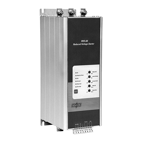
Page 7: Starter Settings
Starter Settings Front Panel Layout Current Limit Determines motor's highest current during starting. ° 600% Range is 100-400% of FLC (as ° ° FLC % 400% set on starter's FLC adjustment). ° ° 100% Too high of a setting will allow 100% °... -
Page 8: Motor Protection
Motor Protection Electronic Overload Heatsink Over temperature Protection The built-in inverse A thermal sensor mounted on the heatsink trips the time electronic starter when its heatsink temperature rises above 85ºC. overload becomes operational after end of acceleration Warning process. Trip The Over-temperature Protection is designed to current is factory set operate under normal conditions and will operate... -
Page 9: Startup Procedure
Startup Procedure 1. Set FLC (Motor Full Load Current) - Examples of Starting Curves according to Light Loads - Pumps, Etc. Current limit - set to 300% Initial Voltage - set to 30% 2. Calculation: Ramp-up time - set to 5 sec. 3. -
Page 10: Technical Specification
Technical Specification Environment * 460 – 500 Vac is applicable for 220 – 240 Vac Supply voltage Three phase, line to line, 380 – 415 Vac +10% -15% by changing the position of the internal jumper – 460 – 500 Vac +10% -15% * J3. -
Page 11: Dimensions
Dimensions \\SOLSRV1\Data\Catalogs and Marketing materials\Instruction Manuals\RVS-AX Instruction Manual 4-5-03.doc...
Need help?
Do you have a question about the Solcon Opal LT Series and is the answer not in the manual?
Questions and answers