ATN Zebra 16 Operator's And Safety Manual
Hide thumbs
Also See for Zebra 16:
- Operator’s and safety handbook (23 pages) ,
- Operator's and safety manual (77 pages) ,
- Operator’s and safety handbook (112 pages)
Table of Contents
Advertisement
Lieu-Dit Bacqué, rue André Thévet
47400 FAUILLET - FRANCE
Phone: 33 (0)5 53 79 83 20
Fax: 33 (0)5 53 79 96 90
Email: contact@atnplatforms.com
www.atnplatforms.com
www.atnplatforms.com
Operator
and
Safety Manual
Zebra 16
Translation of the original manual
11/2009
1NO 0027FR-01
1NO0035UK-05 Revision 10/2019
Advertisement
Table of Contents

Subscribe to Our Youtube Channel
Related Manuals for ATN Zebra 16


Summary of Contents for ATN Zebra 16
- Page 1 Lieu-Dit Bacqué, rue André Thévet 47400 FAUILLET - FRANCE Phone: 33 (0)5 53 79 83 20 Fax: 33 (0)5 53 79 96 90 Email: contact@atnplatforms.com www.atnplatforms.com www.atnplatforms.com Operator Safety Manual Zebra 16 Translation of the original manual 11/2009 1NO 0027FR-01 1NO0035UK-05 Revision 10/2019...
- Page 2 OPERATOR AND SAFETY MANUAL DISTRIBUTOR’S STAMP Zebra 16 1NO0035UK-05...
- Page 3 The information in this manual does not, in any case, replace community, state, local regulations or safety instructions or insurance policy requirements. Due to constant improvements made to its products, ATN reserves the right to alter their specifications and equipment without prior notice.
- Page 4 AND THE REGULATION IN FORCE FOR INCLINES, HILLY SOFT THIS TYPE OF MACHINE. SURFACES. ALL 4 WHEELS MUST REMAIN IN UNTRAINED OPERATOR PUTS PERMANENT CONTACT WITH THE HIMSELF AND OTHERS AT RISK OF GROUND. DEATH OR SERIOUS INJURIES. Zebra 16 1NO0035UK-05...
- Page 5 If you do not know who your distributor is, or cannot inform them, please contact: Tel: 33 (0)5 53 79 83 20 Fax: 33 (05) 53 79 96 90 Address: Lieu-Dit Bacqué, rue André Thévet, 47400 Fauillet, France Zebra 16 1NO0035UK-05...
- Page 6 2004 and the noise emission directive 2000/14/CE of 8th May 2000. This machine also conforms to standard NF EN280. The EC type certificate has been issued by: APAVE 13 à 17 rue Salneuve 75854 PARIS CEDEX 17 Under the reference: 0060/ 5253/ 760/ 09 / 13/ 0002 Zebra 16 1NO0035UK-05...
-
Page 7: Table Of Contents
Section 8. CONTROL MODULE ............................54 8.1. WELCOME SCREEN ..............................54 8.2. MENUS ................................... 55 8.3. SETTINGS - LOGS ................................. 67 8.4. FACTORY SETTINGS ..............................71 Section 9. DIAGRAMS ................................73 9.1. WIRING DIAGRAM ............................... 73 9.2. HYDRAULIC DIAGRAM .............................. 77 Zebra 16 1NO0035UK-05... -
Page 8: Section 1. General Description
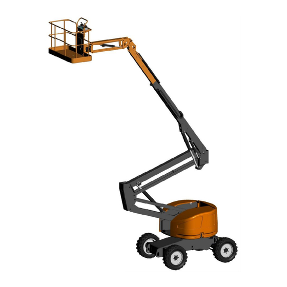
OPERATOR AND SAFETY MANUAL 1.1. DESCRIPTION CONTROL STATION FOR THE WORK PLATFORM WORK PLATFORM ARM 3 TELESCOPE ARM 2 ARM 1 GROUND CONTROL STATION HYDRAULIC TANK DIESEL ENGINE COMPARTMENT FUEL TANK (DIESEL) OSCILLATING REAR AXLE FRONT AXLE STEERING Zebra 16 1NO0035UK-05... -
Page 9: Characteristics - Dimensions
OPERATOR AND SAFETY MANUAL 1.2. CHARACTERISTICS - DIMENSIONS 2250 2100 3010 7120 1800 2240 5120 2250 Zebra 16 1NO0035UK-05... - Page 10 OPERATOR AND SAFETY MANUAL 16.4m 14.4m 360° 7.4m Zebra 16 1NO0035UK-05...
- Page 11 The average maximum quadratic value weighted by the acceleration frequency to which the whole body is exposed does not exceed 0.5m/s². Due to constant improvements made to its products, ATN reserves the right to alter their specifications and equipment without notice.
- Page 12 OPERATOR AND SAFETY MANUAL MOVEMENT DURATIONS Zebra 16 Arm 1 Rise Idle 29 to 32 seconds High regime 17 to 20 seconds Descent Idle 24 to 27 seconds High regime 21 to 24 seconds Arm 2 Rise Idle 25 to 28 seconds...
-
Page 13: Section 2. Safety Instructions
• Knowledge of current regulations concerning this type of machine. (Classification: Group B – Type 3). • Sufficient knowledge of how the machine operates to be able to recognise incorrect operation, a fault or a risk of a fault. Zebra 16 1NO0035UK-05... -
Page 14: Tipping Hazards
• Keep the machine a good distance from holes, bumps, tilt, debris and coatings likely to hide holes or other dangers on the ground. • Do not raise the work platform if the wind speed is greater than 12.5m/s (45km/h). • c. Zebra 16 1NO0035UK-05... -
Page 15: Crushing And Collision Hazards
• Be guided by a person on the ground when visibility is reduced. • Take into account the braking or stopping distances according to the movement speed. Reduce speed when moving on slopes (platform in low position). • The wearing of protective equipment is recommended. Zebra 16 1NO0035UK-05... -
Page 16: Electrocution Hazards
PERSONNEL ON THE GROUND MUST KEEP AWAY IF THE MACHINE IS BEING USED NEAR ELECTRIC LINES OR POWERED EQUIPMENT. IN THE EVENT OF CONTACT WITH AN ELECTRIC LINE OR POWERED APPLIANCE, PERSONNEL ON THE GROUND MUST KEEP AWAY FROM THE MACHINE UNTIL THE ELECTRIC POWER IS CUT. Zebra 16 1NO0035UK-05... -
Page 17: Falling Hazards
(control station, electric cables, hydraulic hoses, cylinders, etc.). Avoid any projection on/to the machine, in particular to the fuel tank. 2.7. OPERATION LIMITS Model Zebra 16 Max floor height 14.40 m Maximum working height 16.40 m... -
Page 18: Towing, Lifting, Transport
• Disconnect the battery during interventions on the machine's electrical circuit or during welding operations. • Do not smoke, bring in bare flames or create sparks near the battery. • Do not place any metal tools or objects on the battery terminals. Zebra 16 1NO0035UK-05... - Page 19 • Do not open the radiator cap when the engine is hot. • No modifications may be made to this machine without written agreement from the manufacturer (Atn). These modifications will invalidate the warranty and the owner and/or user will be held responsible if an accident occurs.
-
Page 20: Section 3. Preparation And Inspection
4- Oscillating axle - Oscillating axle cylinders. 5- Steering cylinder - Steering bar. 6- Front wheel motors - Wheel pivot axes: No screws missing - Screws correctly tightened. 7- Wheels Tyres in good condition – No wheel nuts missing – Wheels correctly tightened Zebra 16 1NO0035UK-05... - Page 21 15- Platform control station: Correctly secured - The levers and switches are present and return to neutral position – The validation pedal is correctly attached and is operating correctly. The emergency stop switch is operating correctly. (14) (15) (1) (2) (3) (6) (7) (14) (13) Zebra 16 1NO0035UK-05...
- Page 22 OPERATOR AND SAFETY MANUAL (12) (11) (12) (11) (11) (12) (12) (11) (10) Zebra 16 1NO0035UK-05...
-
Page 23: Operating Checks
7- Take the structure back into the chassis axis. 8- Perform a slow sideways movement: the axle must unblock and the right wheel must return to contact with the ground. 9- Repeat the previous procedure placing the wedge under the front left wheel. Zebra 16 1NO0035UK-05... - Page 24 1- Platform lowered, drive the machine on a slope greater than the maximum accepted tilt: the tilt light comes on. 2- Raise the platform by around 1m: the alarm sounds. 3- Check the movements are disabled depending on the selected operating mode (see Section 5 - Safeties). Zebra 16 1NO0035UK-05...
-
Page 25: Section 4. Operation
Read the safety instructions in Section 2 of this manual before using the machine. 4.1. CONTROLS AND INDICATORS 4.1.1 GROUND CONTROL STATION (13) (12) (10) (11) 5 sec START Zebra 16 1NO0035UK-05... - Page 26 See Section 4.4.5 – Structure orientation. 6- Arm 1 Up / Down control: Toggle the lever upwards to raise arm 1 or downwards to lower arm 1. See Section 4.4.2 – Elevation. Zebra 16 1NO0035UK-05...
- Page 27 12- Maintenance / System fault light: This light flashes slowly when a maintenance / pre-scheduled maintenance operation is required. This light is on steady (and an alarm sounds) if there is a control system fault. See 5.2.3 – System fault. Zebra 16 1NO0035UK-05...
- Page 28 OPERATOR AND SAFETY MANUAL 12- Preheating light: This light comes on during the preheating phase and goes off once the engine starts. See Section 4.2 – Diesel engine operation. 13- Hourmeter: Indicates the total operating time for the diesel engine. Zebra 16 1NO0035UK-05...
- Page 29 Engine rate selector. 10- Movement speed adjustment gauge. 11- Drive movement and Steering joystick. 12- Drive speed selector switch. 13- Drive movement light and validation (Option). 14- Horn. 15- Generator light and Start up (Option). 16- Indicators. Zebra 16 1NO0035UK-05...
- Page 30 Push the lever forwards to raise arm 2 or pull the lever backwards to lower arm 2. Tilt the lever to the right or to the left to move the structure in the corresponding direction. See Section 4.4.2 – Elevation. See Section 4.4.5 – Structure orientation. Zebra 16 1NO0035UK-05...
- Page 31 The light goes out when the generator is running. Tilt the lever to the left (OFF) to cut the generator. 16- Tilt Indicator: This light comes on when the machine has reached the maximum authorised tilt. See Section 5.1 – Tilt detector. Zebra 16 1NO0035UK-05...
- Page 32 This indicator lights up when the fuel level in the tank reaches a critical level: add fuel in the tank. See 7.1.2 – Fuel. 16- Preheat indicator: This light comes on during the preheating phase and goes off once the engine starts. See Section 4.2 – Diesel engine operation. Zebra 16 1NO0035UK-05...
-
Page 33: Diesel Engine Operation
- When the engine is hot it starts immediately. CAUTION Release the button as soon as the engine starts. LET THE ENGINE WARM UP FOR A • Stop / Emergency stop FEW MINUTES BEFORE USING THE MACHINE. Pressing the Emergency Stop buttons cuts Zebra 16 1NO0035UK-05... - Page 34 Return the platform to its low position and stop the engine immediately. The auxiliary hydraulic group may also be used to lower the platform. The exact nature of the fault is indicated on the control module screen. Zebra 16 1NO0035UK-05...
-
Page 35: Drive - Steering
4- Within 5 seconds, command the drive movement in the direction selected. If the movement is not controlled within 5 seconds, the validation pedal must be released and the validation sequence restarted from step 2. Once the machine is running, release the validation button. Zebra 16 1NO0035UK-05... -
Page 36: Lifting Structure
4- To stop the movement, return the lever/joystick to neutral to reduce the speed and release the validation pedal. 4.4.3 TELESCOPE • From the ground control station 1- Activate and hold down the enable button. The validation button must be activated before a movement is commanded. Zebra 16 1NO0035UK-05... - Page 37 2- Tilt the orientation command lever up to move the structure to the right or down to move the structure to the left. 3- To stop the movement, release the command lever or the validation button. Zebra 16 1NO0035UK-05...
-
Page 38: Parking - Storage
2- From the control station on the ground, lower arm 2, take the telescope back in, lower arm 3 and position the work platform at 90° to the right (to the stop). 3- Raise arm 1 as indicated below: Zebra 16 1NO0035UK-05... - Page 39 OPERATOR AND SAFETY MANUAL 4- Use the platform levelling command to fold it back along the arms: tilt the command lever downwards. 5- Lower arm 1. Zebra 16 1NO0035UK-05...
-
Page 40: Handling - Stowage For Transport
• The machine must be in transport position. • The machine must be solidly secured to the vehicle platform as shown below. Use chains or slings rather than textile straps. In addition, the wheels may be chocked. 1385 1335 Zebra 16 1NO0035UK-05... - Page 41 Remove from the machine everything that could present a falling hazard. Use a hoist adapted to the weight and dimensions of the machine. Attach the slings to the 4 lifting points of the machine as represented on the drawing below. 2200 2720 Zebra 16 1NO0035UK-05...
-
Page 42: Section 5. Safety Devices
Arm 2 lower and orientation cutout until the telescope is taken back in. Combined movements prohibited. • Mode 4 (CAUTION, this mode does not correspond to the EC standard): No movement cutout. Engine high speed cutout for the structure movements. Zebra 16 1NO0035UK-05... -
Page 43: Load Control
If the alarm does not sound, slowly loosen the load spring adjustment nut in counterclockwise direction with 17mm wrenches until the alarm stops. 7. From the ground, lift manually the platform by about 5cm, the alarm must stop. Zebra 16 1NO0035UK-05... -
Page 44: System Fault
If a fault occurs when the platform is raised and is occupied by personnel, appropriate measures must be taken to rescue the platform's occupants. 5.5. MOVEMENT ALARMS A movement alarm may sound: During drive movements During lifting structure movements During drive and lifting structure movements See § 8.3.1 – Safety settings. Zebra 16 1NO0035UK-05... -
Page 45: Anticrushing System (Option)
If you make a lowering movement and activate the pressure sensitive bar, nothing happens. An operator can also take control of the machine from the ground even when the sensitive bar is activated. Zebra 16 1NO0035UK-05... -
Page 46: Section 6. Emergency Procedures
2- Use the commands to take the platform back to low position. • From the work platform control station 1- Press the validation pedal. 2- Keep the Start / Auxiliary Group button tilted downwards. 3- Use the commands to take the platform back to low position. Zebra 16 1NO0035UK-05... -
Page 47: Emergency Towing
7- Using appropriate equipment, tow the machine at slow speed on level ground only. 8- Once the towing has been performed, block the machine's wheels, remove the flanges to restore the brakes and tighten the by-pass valve. Zebra 16 1NO0035UK-05... -
Page 48: After An Incident
After an incident, inspect the machine carefully and test the good working order of all controls and safeties. Only raise the platform by a metre if all the damages have been repaired and if all the controls are operating correctly. If in doubt, contact your reseller or the manufacturer. Zebra 16 1NO0035UK-05... -
Page 49: Section 7. Maintenance For The Operator
Grade 15W40 lubricant. This type of lubricant RECOMMENDED enables the engine to start at temperatures as low as -15°C. Depending on the operating conditions of the machine, you may need to adapt the type of lubricant (See graph opposite). AMBIENT TEMPERATURE (°C) Zebra 16 1NO0035UK-05... -
Page 50: Lubrication
(16) (19) (18) (16) (16) (18) (18) (16) (16) (18) (16) (18) (16) (18) (18) (16) (16) (17) (18) (16) (16) (18) (10) (15) (16) (17) (1) (2) (21) (15) (20) (22) Zebra 16 1NO0035UK-05... -
Page 51: Wheels
100 hours' operation. TIGHTEN THE WHEEL NUTS. • Wheel replacement To avoid harming the machine's stability, the wheels may only be replaced by wheels with identical characteristics (dimensions, load capacity, crushing under load, true position, mass, etc.). Zebra 16 1NO0035UK-05... -
Page 52: Battery
- Use a 12 Volt charger adapted to the battery's capacity. - Disconnect the battery from the machine before charging it. - To preserve the battery's lifetime, avoid quick recharges. - Only charge the battery in well-ventilated premises. Zebra 16 1NO0035UK-05... - Page 53 1.15 dry premises away from frost. Charge the battery if the battery voltage in open circuit is under 12.40 volts. 1.10 Check the electrolyte level and 100% recharge the battery approximately Discharge depth every two months. Zebra 16 1NO0035UK-05...
-
Page 54: Section 8. Control Module
The following screen is displayed when the machine is powered up: (12) (11) (10) 1- Machine model and serial number 2- Date / time, 3- System status: System OK / Error active. 4- Light - System fault. 5- Lights - Faults: Zebra 16 1NO0035UK-05... -
Page 55: Menus
8.2. MENUS Welcome screen Ecran d'accueil Platform Transmission Transmission Etat des Diagnostic Service Infos Command Direction steering Commandes Service Diagnostic Moteur thermique Status de la Plate-forme Diesel engine Ground Station Etat des Safeties Command Commandes Poste Bas Status Zebra 16 1NO0035UK-05... - Page 56 3- Parameters - Steering movement. The arrows light up when the corresponding movement is commanded. Proportional valve control setpoint (PV2) Steering hydraulic circuit pressure 4- Light - Parking brake: the icon turns grey when the brake is deactivated. Zebra 16 1NO0035UK-05...
- Page 57 10- Engine speed (RPM) 11- Light – Engine speed fault (option). The light comes on if the slow down speed is too high 12- Lights – Diesel engine faults. Engine oil pressure fault Engine temperature fault Alternator fault Zebra 16 1NO0035UK-05...
- Page 58 Joystick setpoint value - Arm 2 movement 2- Entry parameters - Arm 1. The arrows light up when the corresponding movement is commanded. Status light - Arm 1 position sensor (the light is on when the arm is in low position). Zebra 16 1NO0035UK-05...
- Page 59 12- Light - Diesel engine start button activated. 13- Light - Tilt / Tilt angle values. Green light: acceptable tilt not reached. Red light: acceptable tilt exceeded. 14- Light - Overload Green light: acceptable load not reached. Red light: acceptable load exceeded. Zebra 16 1NO0035UK-05...
- Page 60 Status light - Arm 2 position sensor (the light is on when the arm is in low position). 3- Entry parameters - Arm 1. The arrows light up when the corresponding movement is commanded. Status light - Arm 1 position sensor (the light is on when the arm is in low position). Zebra 16 1NO0035UK-05...
- Page 61 9- Light - Validation / Auxiliary group button activated. 10- c. 11- Light - Tilt / Tilt angle values. Green light: acceptable tilt not reached. Red light: acceptable tilt exceeded. 12- Light - Overload Green light: acceptable load not reached. Red light: acceptable load exceeded. Zebra 16 1NO0035UK-05...
- Page 62 5- Status light - Arm 2 position sensor (the light is on when arm 2 is in low position). 6- Light - Overload / Operating mode: Operating mode selected (see § 5-2) Overload light (Green / Red) 7- Light - System fault. Zebra 16 1NO0035UK-05...
- Page 63 Use the right hand arrows to display the access code digits. Press [OK] to validate each digit and move onto the next one. Once the last digit has been entered, press [OK] then [F2] (or [OK] again). Zebra 16 1NO0035UK-05...
- Page 64 If the machine is used very intensively or in a harsh environment, the intervals may be reduced. It is preferable to only modify the revision interval when the revision is carried out. Press [F1]. Press [F3]. 200h 200h 255h Zebra 16 1NO0035UK-05...
- Page 65 Use the right hand arrows to modify the interval between each revision. Press [OK] again to Press [OK] to validate. validate the new interval. 150h 150h 255h Press [F3] to confirm the setting then press [F4] to finish. 150h 150h 150h Zebra 16 1NO0035UK-05...
- Page 66 Press the back to previous screen arrow: Press [F2]. 150h 255h 150h Press [F2] to confirm. The number of hours is updated according to the new interval: 205h Zebra 16 1NO0035UK-05...
-
Page 67: Settings - Logs
- Arm 1 lower - Arm 2 raise - Arm 2 lower - Telescope out - Telescope in - Arm 3 raise - Arm 3 lower - Rotating platform - Levelling - Raise - Levelling - Lower - Orientation Zebra 16 1NO0035UK-05... - Page 68 - RPM limit slowed down - Max Slowed Down Speed Authorised - Drive Movement Reduction in Tilt Option Settings - Generator Active Inactive - Flashing light Inactive Machine powered up Engine running On drive movement On drive movement + movements Zebra 16 1NO0035UK-05...
- Page 69 8.3.2 INFO – RECORDS (LOGS) The system saves each command and each "system fault". Certain data concerning the machine's usage rate or certain functions is also saved to plan any preventive maintenance operations. Press [F4]. Press [F3]. Zebra 16 1NO0035UK-05...
- Page 70 - Elevation function usage time - Sideways movement function usage time Auxiliary group - Date and usage duration of the auxiliary group Auxiliary group (Total) - Total duration and date of last use of the auxiliary group Zebra 16 1NO0035UK-05...
-
Page 71: Factory Settings
Use the right hand arrows to display the access code digits. Press [OK] to validate each digit and move onto the next one. Once the last digit has been entered, press [OK] then [F2] (or [OK] again). Press [F1]. Press [F1]. 155h Zebra 16 1NO0035UK-05... - Page 72 OPERATOR AND SAFETY MANUAL Note: the values indicated in the table below are provided for information purposes. Zebra 16 1NO0035UK-05...
-
Page 73: Section 9. Diagrams
OPERATOR AND SAFETY MANUAL 9.1. WIRING DIAGRAM Zebra 16 1NO0035UK-05... - Page 74 OPERATOR AND SAFETY MANUAL Zebra 16 1NO0035UK-05...
- Page 75 OPERATOR AND SAFETY MANUAL Zebra 16 1NO0035UK-05...
- Page 76 OPERATOR AND SAFETY MANUAL Zebra 16 1NO0035UK-05...
-
Page 77: Hydraulic Diagram
OPERATOR AND SAFETY MANUAL 9.2. HYDRAULIC DIAGRAM Zebra 16 1NO0035UK-05... - Page 78 OPERATOR AND SAFETY MANUAL Zebra 16 1NO0035UK-05...
- Page 79 OPERATOR AND SAFETY MANUAL NOTES Zebra 16 1NO0035UK-05...
- Page 80 OPERATOR AND SAFETY MANUAL NOTES Zebra 16 1NO0035UK-05...
Need help?
Do you have a question about the Zebra 16 and is the answer not in the manual?
Questions and answers