Table of Contents
Advertisement
Advertisement
Table of Contents

Related Manuals for ATN PIAF 10E 2018


Summary of Contents for ATN PIAF 10E 2018
- Page 1 Lieu –Dit Bacqué, rue André Thevet 47400 FAUILLET - FRANCE Tél: 33 (0)5 53 79 80 60 Fax: 33 (0)5 53 79 96 90 Email: contact@atnplatforms.com www.atnplatforms.com Safety Maintenance Manual T ra n sla ti on of t he o ri gi nal m anu al 1NO0055UK-00 Rev 03/2018...
- Page 2 SAFETY AND MAINTENANCE MANUAL DISTRIBUTOR STAMP PIAF 1NO0055UK-00...
- Page 3 SAFETY AND MAINTENANCE MANUAL DANGER DANGER IN WORK MODE, THE PLATFORM CAN DO NOT USE THIS MACHINE IF YOU ONLY BE DRIVEN ON HARD AND HAVE NOT BEEN PROPERLY TRAINED HORIZONTAL GROUNDS FREE FROM TO ITS SAFE OPERATION. TRAINING ANY OBSTACLE. INCLUDES KNOWLEDGE OF YOUR EMPLOYER’S WORK REGULATIONS, WHEELS...
- Page 4 SAFETY AND MAINTENANCE MANUAL FOREWORD This manual has been compiled to assist to properly use and maintain your self-propelled work platform. Take the time to carefully read and familiarise yourself with its content. Once you have read and understood all sections, keep this manual in the manual storage box provided to this effect in the PIAF platform.
- Page 5 Jib elevation / lowering and structure rotation Mast elevation lowering control switch Should you find a non-conformity… Write immediately a claim and send a copy to ATN and to the transport company. You have 48 hours after the delivery to file your claim. WARNING...
- Page 6 SAFETY AND MAINTENANCE MANUAL DANGER DO NOT USE THIS MACHINE IF YOU HAVE NOT BEEN TRAINED TO ITS SAFE OPERATION. DANGER READ THE OPERATOR’S AND SAFETY MANUAL BEFORE OPERATING THE MACHINE. PIAF 1NO0055UK-00...
- Page 7 SAFETY AND MAINTENANCE MANUAL GUARANTEE FOR ANY NEW EQUIPMENT, THERE IS NO GUARANTEE, EXPLICIT OR IMPLICIT, OTHER THAN THAT OF THE SELLER COVERING FAULTY MATERIAL OR THE DEFECTS OF FABRICATION DRAWN UP IN THE FOLLOWING TERMS: GUARANTEE OF NEW EQUIPMENT “The Manufacturer guarantees each new product against any faulty material or defect of fabrication, as his obligation and responsibility are limited under this guarantee to the repair or replacement free of charge in his factory of any part recognized as defective in normal use and...
- Page 8 SAFETY AND MAINTENANCE MANUAL PIAF 1NO0055UK-00...
- Page 9 75854 PARIS CEDEX 17 Under the reference: 0060/5253/760/02/17/0012 The technical file has been compiled by: Jean-François DUCLOS (for ATN) ZI Guillaume Mon Amy 47400 FAUILLET (France) Fauillet, 02/01/2019 Note : any modification to the material designated above voids this declaration.
- Page 10 SAFETY AND MAINTENANCE MANUAL PIAF 1NO0055UK-00...
-
Page 11: Table Of Contents
SAFETY AND MAINTENANCE MANUAL TABLE OF CONTENTS Chapter I .............................. 13 OPERATION AND SAFETY ........................13 1. GENERAL DESCRIPTION ..................15 ECTION 1.1. MACHINE DESCRIPTION, DIMENSIONS ..................15 1.2. RANGE DIAGRAMMES ........................15 1.3. TECHNICAL CHARACTERISTICS....................17 2. SAFETY INSTRUCTIONS ..................19 ECTION 2.1. - Page 12 SAFETY AND MAINTENANCE MANUAL Chapter II ............................43 MAINTENANCE........................... 43 1. MECHANICS ......................45 ECTION 1.1. CHASSIS ON WHEELS ........................45 1.2. MAST SECTIONS ..........................50 1.3. JIB AND CYLINDER ......................... 54 1.4. PLATFORM AND PLATFORM SUPPORT ..................55 1.5. STRUCTURE ............................. 57 1.6.
-
Page 13: Chapter I
SAFETY AND MAINTENANCE MANUAL Chapter I OPERATION AND SAFETY PIAF 1NO0055UK-00... - Page 14 SAFETY AND MAINTENANCE MANUAL PIAF 1NO0055UK-00...
-
Page 15: Section 1. General Description
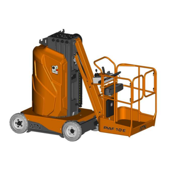
11 m SAFETY AND MAINTENANCE MANUAL 10 m 9,92 1.1. MACHINE DESCRIPTION, DIMENSIONS 7,92 Telescopic mast Upper control station Lower Jib 6,55 Batteries Counterweight 5,18 REAR FRONT Basket (work platform) Steering wheels Braked driving wheels Hydraulic power unit Lower control station 3,51 -4 m -2 m... - Page 16 SAFETY AND MAINTENANCE MANUAL 11 m 10 m 9,92 7,92 6,55 5,18 3,51 -4 m -2 m -3 m -1 m PIAF 1NO0055UK-00...
-
Page 17: Technical Characteristics
The average root mean square value of weighted acceleration to which the whole body is subjected does not exceed 0.5m/s². Due to our constant improvement policy, Atn reserves the right to make any modifications without prior notice. DESCRIPTION PIAF 10E... - Page 18 SAFETY AND MAINTENANCE MANUAL PIAF 1NO0055UK-00...
-
Page 19: Section 2. Safety Instructions
SAFETY AND MAINTENANCE MANUAL The definitions of DANGER, WARNING, and NOTE in this manual are used as follows: DANGER INDICATES A DANGEROUS SITUATION WHICH MAY LEAD TO SERIOUS OR LETHAL INJURIES SAFETY INSTRUCTIONS ARE NOT STRICTLY FOLLOWED. WARNING INDICATES PROCEDURE OPERATION TO BE FOLLOWED TO THE LETTER TO AVOID ANY RISK OF DAMAGING THE MACHINE. -
Page 20: The Operator
SAFETY AND MAINTENANCE MANUAL 2.1. THE OPERATOR You, as the operator, are the only thinking part of the machine; your responsibility is not lessened by the addition of alarms or operating aids. In fact, you must not get a false sense of safety when operating the machine. -
Page 21: Machine Stability
SAFETY AND MAINTENANCE MANUAL You must wear appropriate clothing and the necessary protection equipment (helmet, harness, gloves…) required by the work regulations. Do not allow anybody to tamper with or to operate the machine from the ground with personnel in the work platform except in emergency situations where it is impossible to lower the platform and exit the basket. -
Page 22: Falling Hazard
SAFETY AND MAINTENANCE MANUAL 2.4. FALLING HAZARD You must take every precaution to avoid falling from the platform especially if it is raised. Before entering the platform, ensure the floor and your shoes are clean and exempt from dirt, and other slippery substances. -
Page 23: Operating Limitations
THIS MACHINE MUST NOT BE USED IF NOT IN PERFECT WORKING ORDER. No modification affecting its original design can be made on this machine without prior Atn, written approval from Such modification will invalidate the guarantee and the owner / operator will be held responsible in case of an accident. - Page 24 SAFETY AND MAINTENANCE MANUAL PIAF 1NO0055UK-00...
-
Page 25: Section 3. Preparation And Inspection
SAFETY AND MAINTENANCE MANUAL Before use, careful inspection and operating check are recommended to ensure that the machine is in perfect working order. Do not use the machine if it is damaged or has an operating defect. Depending on national or local regulations, the machine must be submitted to periodic verifications and testing. - Page 26 SAFETY AND MAINTENANCE MANUAL 6- Control station on the ground: The control station switches are present and return to neutral position – The emergency stop switch is operating correctly. 7- Hydraulic cylinders. 8- Articulation pins: Presence of the pin lock screws. 9- Garde-corps : Etat –...
-
Page 27: Section 4. Operation
SAFETY AND MAINTENANCE MANUAL OPERATING RECOMMENDATIONS Do not use the platform for any purpose other than that intended by the manufacturer. It has been designed to position personnel, tools and NECESSARY material at a work station at heights, not for handling bulk materials. Never exceed the rated load of the platform (200Kg). - Page 28 SAFETY AND MAINTENANCE MANUAL 1- Control station selector switch: Used to activate the controls on the work platform control station or the ground control station. In position O, the key may be removed. 2- Enable button : This button must be pushed and held to control the movements from the ground control station.
- Page 29 SAFETY AND MAINTENANCE MANUAL 10- Brake release control switch : This switch releases the brakes for emergency towing (see § 4.2.4 and § 4.5.4) 4.1.2 PLATFORM CONTROL STATION Control joystick for Jib Up / Down + structure rotation movements Control joystick for drive and steering movements Mast Up / Down control switch Horn Emergency stop switch...
- Page 30 SAFETY AND MAINTENANCE MANUAL 1- Joystick 2 axis Jib elevation / lowering and structure rotation: Push the lever forward to raise the jib or pull the lever backwards to lower the jib. Tilt the lever to the right or to the left to rotate the structure in the corresponding direction.
- Page 31 SAFETY AND MAINTENANCE MANUAL 7- Overload indicator light : This light flashes when the platform’s load capacity has been exceeded. -NOTE- The machine stops when this indicator lights up. You must unload the basket to restore the machine’s functions 8- Chain Slack indicator light: Warns the operator of a problem during the lowering of the mobile mast sections.
-
Page 32: Breakdown Controls
SAFETY AND MAINTENANCE MANUAL 4.2. BREAKDOWN CONTROLS The structure can be rotated, the mast or jib can be lowered using the breakdown controls. 4.2.1 STRUCTURE MANUAL ROTATION 1. Open the tap on the manifold to disengage the structure rotation motor. 2. - Page 33 SAFETY AND MAINTENANCE MANUAL 4.2.2 MAST MANUAL LOWERING CONTROL The mast lowering control is located on the solenoid of the mast cylinder. The mast will come down by gravity when this control is operated. It is a proportional control: the more it is pushed in, the quicker the movement.
- Page 34 SAFETY AND MAINTENANCE MANUAL 4.2.4 BRAKE RELEASE FOR TOWING The brake release control is located on the right DANGER hand side of the ground control box. Actuation of the control will release the brakes of RELEASE THE BRAKES ONLY IF THE the machine and the brake light will come on.
-
Page 35: Safety Devices And Alarms
SAFETY AND MAINTENANCE MANUAL 4.3. SAFETY DEVICES AND ALARMS 4.3.1 EMERGENCY STOPS The machine is fitted with 2 Emergency Stop Switches: One on the upper electrical box. One on the lower electrical box. Pushing on one of these 2 switches will cut off the electrical supply to the platform. 4.3.1 HORN The horn is located on the lower electrical box. -
Page 36: Starting
SAFETY AND MAINTENANCE MANUAL WARNING As soon as the indicator light switches off and the buzzer stops, the operator can resume normal operations. ASK PERSONNEL ON THE GROUND TO RELEASE THE MACHINE AND STAY CENTRE BASKET WHILE HOLDING TIGHT ONTO THE GUARDRAIL. - Page 37 SAFETY AND MAINTENANCE MANUAL NORMAL OPERATION 1- Plug the charger to a mains socket. DANGER 2- The RED Led indicates the start of the charging cycle. DO NOT USE THE MACHINE DURING 3- The YELLOW Led indicates THE CHARGE. FAILURE TO DO SO the battery is 80% charged.
- Page 38 SAFETY AND MAINTENANCE MANUAL 4.4.2 HYDRAULIC TANK Check the hydraulic oil level through the transparent tank. Check the levels only when the machine is fully lowered. 4.4.3 TILT SENSOR - Place the machine on a slope with a grade greater than 2°. - The alarm in the lower electrical box sounds.
-
Page 39: Transportation Of The Platform
SAFETY AND MAINTENANCE MANUAL 4.5. TRANSPORTATION OF THE PLATFORM 4.5.1 DRIVING ON A SLOPE To prevent any accident while driving on a slope, ensure its grade is lower than 25%. The platform must be fully lowered, in slow speed and the basket must always be on the lower side of the slope. - Page 40 SAFETY AND MAINTENANCE MANUAL 4.5.5 LIFTING THE MACHINE LIFTING Prior to any operation, check the capacity of the equipment used (min 3000 Kg) DANGER STAY WELL CLEAR OF THE MACHINE DURING LIFTING OPERATIONS. 4.5.6 TIE DOWN ON THE BED OF A TRUCK TIE DOWN The machine must be tied down to ensure stability during transportation.
-
Page 41: Section 5. Regulations
5.1. VERIFICATION DURING COMMISSIONNING - Conformity to the decree from March 1 2004. - New machine, this verification is done by Atn (following the standards in force). - This 1st check is valid for 6 months. 5.2. PERIODIC VERIFICATIONS IN FRANCE - Conformity to the decree from March 1 2004. - Page 42 SAFETY AND MAINTENANCE MANUAL PIAF 1NO0055UK-00...
-
Page 43: Chapter Ii
SAFETY AND MAINTENANCE MANUAL Chapter II MAINTENANCE PIAF 1NO0055UK-00... - Page 44 SAFETY AND MAINTENANCE MANUAL PIAF 1NO0055UK-00...
-
Page 45: Section 1. Mechanics
SAFETY AND MAINTENANCE MANUAL DESCRIPTION 1.1. CHASSIS ON WHEELS TRIPHASED MOTOREDUCER 850W STEERING PIVOT RHS STEERING PIVOT LHS DRIVE SYSTEM SUPPORT RS70 STEERING BAR The platform drive system consists of 2 PROTECTION RS70 PIN Ø15 L135 triphased electric moto-reducers located PIVOT RING Ø60/28 - 5 at the rear of the chassis. - Page 46 SAFETY AND MAINTENANCE MANUAL 1.1.1 OPERATING MODE Electro-hydraulic power is delivered by pressing the enable pedal and using the joystick. As soon as the platform rises, the speed-limiting sensors are activated and only slow speed is available. Steering occurs through an hydraulic cylinder controlled using the joystick. 1.1.2 WHEELS Regular service on the wheels will ensure a longer service life.
- Page 47 SAFETY AND MAINTENANCE MANUAL REMOVAL OF THE STEERING BAR (5). 9- Remove the split pins (32) and washers (28). 10-Release the steering bar (5). REMOVAL OF THE ANGLE SENSOR (12) 11- Loosen the bolts (19) and washers (29) securing the sensor protection cover (6). 12- Remove the angle sensor (12) and its pin (10).
- Page 48 SAFETY AND MAINTENANCE MANUAL 11- Install the pivot on the chassis with the pivot pin (11). Ensure the middle hole of the pivot pin is in line with the hole from the pivot square. 12- Secure the pivot pin (11) with the bolt (18) washer (27) and nut (24). INSTALLATION OF THE ANGLE SENSOR (12) 13- Position the sensor support without the bolts to secure it.
- Page 49 SAFETY AND MAINTENANCE MANUAL STEERING BAR INSTALLATION (5). 20- Install the washers (28) on the pivots. 21- Install the steering bar (5) making sure the wheels are straight. 22- Install the washers (28) then the split pins (32), new if necessary. Reconnect the hydraulic hoses as tagged previously to the cylinder (15).
-
Page 50: Mast Sections
SAFETY AND MAINTENANCE MANUAL SURVEILLANCE OF THE PROTECTION Visual examination can determine the integrity of the protection seals: - absence of excessive tensions and tears. - correct position. - wear of the floating lip. If necessary, replace the seal. After lubrication, remove the used greased and check for absence of pollution like sand, brush dust, metal particles, etc…... - Page 51 SAFETY AND MAINTENANCE MANUAL ROLLER ADJUSTMENT Check and adjust the transversal play of the mast sections. 1- Loosen the counternuts from the roller pins. 2- Reduce the play by tightening the roller pins. Do not suppress the play completely. - NOTE- A minimum play between the friction surfaces rollers necessary...
- Page 52 SAFETY AND MAINTENANCE MANUAL WARNING WARNING ADJUSTMENT OF THE TRANSVERSAL ENSURE THE INSIDE OF THE MAST PLAY BETWEEN THE MAST SECTIONS SECTIONS ARE KEPT CLEAN AND MUST BE PERFORMED BY TRAINED GREASED TO PREVENT THE MAST AND QUALIFIED PERSONNEL. FROM JAMMING. ADJUSTMENT OF THE MAST HEIGHT WARNING It is necessary to correctly adjust the mobile mast...
- Page 53 SAFETY AND MAINTENANCE MANUAL 1.2.3 LIFTING CHAINS LIFTING CHAIN MAINTENANCE Regularly check: The geometry of the assembly, in particular the alignment of the anchors with the pulleys and the wear of the pulley The condition of the chain, in particular to detect possible friction indicating an incorrect geometry of the assembly or contacts with structure parts.
-
Page 54: Jib And Cylinder
SAFETY AND MAINTENANCE MANUAL EXAMPLE OF INSPECTION FOR WEAR > Pins turned indicate an incorrect lubrication and a risk of seizure. > Loose pins. It happens when the pins are turned or when the joints are rigid. > Cracked plate due to hydrogen. This is often caused by cold or steam cleaning. -
Page 55: Platform And Platform Support
SAFETY AND MAINTENANCE MANUAL 1.4. PLATFORM AND PLATFORM SUPPORT 1.4.1 PLATFORM The machine is fitted with a stand alone platform. It can be removed quickly without removing the hydraulic or electric controls. No particular maintenance is required. Fig 1 Fig 2 PLATFORM REMOVAL - Loosen and remove the 4 locknuts on the U-clamps (Fig.1). - Page 56 SAFETY AND MAINTENANCE MANUAL Fig 3 Fig 4 - Tilt the platform to release it from the platform support to prevent damages with removing it. (Fig.3 and 4). PLATFORM INSTALLATION - Tilt the platform to fit the controls correctly. - Lower the platform. - Install the U-clamps on the platform while holding it tight on its support.
-
Page 57: Structure
The machine structure is made of all welded steel with special profiles and specific steel grades. Elements of this structure therefore cannot be modified or replaced without prior approval by Atn. It is advised to visually inspect every 6 months the different elements to detect potential faults. - Page 58 SAFETY AND MAINTENANCE MANUAL PLATFORM SUPPORT - Inspect the welds around the control support plate. - Inspect the welds around support plate tubes. - Inspect the welds around the jib and tie rod pin. - Inspect the welds around the pin bearing. - Inspect the welds of the platform support.
-
Page 59: Torque Values
SAFETY AND MAINTENANCE MANUAL 1.6. TORQUE VALUES Use of proper torque values is extremely important. Improper torquing can seriously affect performance and reliability. - NOTE - Some special applications require variation from the standard torque values. Reference should always be made to component overhaul procedures for recommendations. If one of the element has been protected (either bolt or nut), the value must be multiplied by 0.90. -
Page 60: Section 2. Hydraulics
SAFETY AND MAINTENANCE MANUAL 2.1. HYDRAULIC POWER UNIT DESCRIPTION DANGER The machine is fitted with a power unit consisting of BEFORE ANY MAINTENANCE, ENSURE a pump and a 24V fan-cooled motor. It is located on ELECTRIC SYSTEM the left hand side of the machine. DISCONNECTED FROM THE POWER SUPPLY. - Page 61 SAFETY AND MAINTENANCE MANUAL EXCESSIVE HEAT Excessive heat usually results from a relief valve set too low. If a relief valve is set too low, part of the oil will be dumped by the relief valve at each cycle. In this case, the machine will be very slow. OIL PRESSURE TOO HIGH There are two possible reasons: (a) the relief valve does not function, producing an extreme surge and immediate failure, or...
- Page 62 SAFETY AND MAINTENANCE MANUAL IF THE OIL HEATS UP: Relief valve set too low Incorrect oil type. Faulty component. Solutions: ◘ Check the setting of the relief valve using a pressure gauge and adjust if necessary. ◘ If incorrect oil type, drain and fill with recommended oil. Refer to the “Lubrication” section. ◘...
- Page 63 SAFETY AND MAINTENANCE MANUAL IF THERE IS NO PRESSURE The pump does not deliver fluid or fluid returns to the tank and does not travel to the components. Solutions: ◘ If fluid returns to the tank and does not go to the components, check the relief valve settings.
-
Page 64: Lubrication
SAFETY AND MAINTENANCE MANUAL OIL CHANGE AND OIL FILTER REPLACEMENT The first oil change and oil filter replacement should be done after the first 50 hours of operation. Thereafter, the oil should be changed every 250 hours of operation. It is recommended to change the oil and replace the filter when the machine oil is warm. - Page 65 SAFETY AND MAINTENANCE MANUAL WARNING WARNING GREASE MUST NOT BE APPLIED MULTI PURPOSE GREASE APPLIED AT USING PNEUMATIC EQUIPMENT AS FACTORY IS OF LITHIUM BASE. USE SEALS COULD GET DAMAGED. NON-COMPATIBLE GREASE COULD RESULT IN DAMAGE TO THE EQUIPMENT. 2.2.1 LUBRICATION POINTS Mast (Grease) Type of lubricant: EP-MPG (USA)
-
Page 66: Hydraulic Schematic
SAFETY AND MAINTENANCE MANUAL 2.3. HYDRAULIC SCHEMATIC PIAF 1NO0055UK-00... -
Page 67: Section 3. Electrics
SAFETY AND MAINTENANCE MANUAL 3.1. BATTERIES DESCRIPTION The electrical energy of the system is 24 volts. Four 6 Volt batteries are connected in series. A complete electrical schematic is supplied at the end of this manual. DANGER DANGER ENSURE THE CHARGER PLUG IS THE BATTERY IS AN INTEGRAL PART DISCONNECTED FROM THE POWER COUNTERWEIGHT. - Page 68 SAFETY AND MAINTENANCE MANUAL Ensure the can is filled with distilled water to its WARNING maximum level. Connect the filling hose to the can. The electrolyte level is correct when the balls in CHECK THE ELECTROLYTE LEVEL the indicator stop turning. ONLY AFTER THE CHARGE.
- Page 69 SAFETY AND MAINTENANCE MANUAL FREEZING POINT Ex: When the battery electrolyte has a gravity of 1.075, its freezing point is -5°C. When the battery is fully charged, the electrolyte gravity is approximately 1.28, its freezing point is -85°C. Therefore the more the battery is charged, the less it is likely to freeze. - NOTE - The battery must be fully charged when the machine is operated in a cold chamber or outside in cold weather conditions.
-
Page 70: Charger
SAFETY AND MAINTENANCE MANUAL TROUBLESHOOTING If small problems encountered on a battery are rapidly and correctly determined, battery life can be improved. PREVENTION = AUTONOMY AND LONG LIFE SYMPTOM PROBABLE CAUSES SOLUTIONS Cells overfilled Never exceed the maximum level Overheat Check the charger capacity. - Page 71 SAFETY AND MAINTENANCE MANUAL 1. Plug the charger on the power socket. 2. The RED Led indicates the start of the charging cycle. 3. The YELLOW Led indicates the battery is 80% charged. 4. The GREEN Led indicates the battery is 100% charged. 5.
- Page 72 SAFETY AND MAINTENANCE MANUAL WARNING DANGER THE MOTOR MUST BE STOPPED IT IS STRICTLY FORBIDDEN TO WASH DURING THE CHARGE. THE MACHINE WHILE THE CHARGER IT IS STRONGLY RECOMMENDED NOT IS RUNNING. HIGH PRESSURE WASH CHARGER. ABSOLUTELY NECESSARY, WAIT UNTIL CHARGER BEFORE CONNECTING IT TO THE POWER...
-
Page 73: Battery Discharge Indicator And Hourmeter
SAFETY AND MAINTENANCE MANUAL 3.3. BATTERY DISCHARGE INDICATOR AND HOURMETER GÉNÉRAL The battery discharge indicator and hourmeter is located on the lower electrical box. It is a single indicator and has two major functions: 1- The battery capacity is indicated by 5 LEDs : 3 green : 100% =>... -
Page 74: Electric Motor
SAFETY AND MAINTENANCE MANUAL 3.4. ELECTRIC MOTOR The electric motor, coupled to an hydraulic pump is a 24V motor. It requires little maintenance. However every 100 hours and at least once a month, you should blow air through the ventilation holes to remove dirt and brushes dust. -
Page 75: Tilt Indicator
SAFETY AND MAINTENANCE MANUAL 3.6. TILT INDICATOR When the platform is 2° off the horizontal, the sensor actuates the acoustic alarm and the corresponding indicator on the upper control panel. The machine switches automatically to slow speed. Actuation of these alarms indicates the machine has reached its stability limits. It is therefore necessary to control this sensor each day before the machine is used. -
Page 76: Overload Detection
SAFETY AND MAINTENANCE MANUAL CHAIN SLACK SENSOR CONTROL PROCEDURE Place a block between the actuator and the sensor to activate the sensor. Ensure the emergency stop switches are pulled out. The indicator, corresponding to the chain slack detection on the upper control box must light The buzzer sounds. -
Page 77: General Inspection Checklist
SAFETY AND MAINTENANCE MANUAL 3.9. GENERAL INSPECTION CHECKLIST COMPONENTS INSPECTION / VERIFICATION / MAINTENANCE INTERVALS D = Daily / W = Weekly / M = Monthly / Y = Yearly Battery Battery charge Electrolyte level Electrolyte density (after the charge) Battery and terminal cleaning Hydraulic oil Oil level... -
Page 78: Electric Schematic
SAFETY AND MAINTENANCE MANUAL 3.10. ELECTRIC SCHEMATIC PIAF 1NO0055UK-00... - Page 79 SAFETY AND MAINTENANCE MANUAL PIAF 1NO0055UK-00...
- Page 80 SAFETY AND MAINTENANCE MANUAL NOTES PIAF 1NO0055UK-00...
- Page 81 SAFETY AND MAINTENANCE MANUAL NOTES PIAF 1NO0055UK-00...
Need help?
Do you have a question about the PIAF 10E 2018 and is the answer not in the manual?
Questions and answers