ATN Zebra 12 Operator’s And Safety Handbook
Mobile elevating work platform
Hide thumbs
Also See for Zebra 12:
- Operator's and safety manual (75 pages) ,
- Operator's and safety manual (45 pages)
Table of Contents
Advertisement
Lieu-Dit Bacqué, rue André Thévet
47400 FAUILLET - FRANCE
Tél: 33 (0)5 53 79 83 20
Fax: 33 (0)5 53 79 96 90
Email: contact@atnplatforms.com
www.atnplatforms.com
Operator's and
Safety
Handbook
Zebra 12 - Zebra 16
– Zebra 16 Stab
11/2009
Translation of the original handbook
1NO 0027FR-01
1NO0060EN-00 revision 02/2021
Advertisement
Table of Contents

Subscribe to Our Youtube Channel
Related Manuals for ATN Zebra 12


Summary of Contents for ATN Zebra 12
- Page 1 Tél: 33 (0)5 53 79 83 20 Fax: 33 (0)5 53 79 96 90 Email: contact@atnplatforms.com www.atnplatforms.com Operator’s and Safety Handbook Zebra 12 - Zebra 16 – Zebra 16 Stab 11/2009 Translation of the original handbook 1NO 0027FR-01 1NO0060EN-00 revision 02/2021...
- Page 2 OPERATOR’S AND SAFETY HANDBOOK DISTRIBUTOR’S STAMP Zebra 12 – Zebra 16 1NO0060EN-00...
- Page 3 OPERATOR’S AND SAFETY HANDBOOK FOREWORD This manual has been compiled to assist to properly use and maintain your Zebra 12, Zebra 16 or Zebra 16 STAB self-propelled work platform. Prior to any operation of the machine (and regularly thereafter), any person in contact with, or having an activity in relation with the machine must read and understand the content of the handbook.
- Page 4 MOVE WITH THE PLATFORM RAISED THIS TYPE OF MACHINE. INCLINES, HILLY SOFT SURFACES. UNTRAINED OPERATOR PUTS WHEELS HIMSELF AND OTHERS AT RISK OF OUTRIGGERS) MUST REMAIN DEATH OR SERIOUS INJURIES. PERMANENT CONTACT WITH THE GROUND. Zebra 12 – Zebra 16 1NO0060EN-00...
- Page 5 If you do not know who your distributor is, or cannot inform them, please contact: Tel: 33 (0)5 53 79 83 20 Fax: 33 (05) 53 88 01 07 Address: Lieu-Dit Bacqué, rue André Thévet, 47400 Fauillet, France Zebra 12 – Zebra 16 1NO0060EN-00...
- Page 6 OPERATOR’S AND SAFETY HANDBOOK Zebra 12 – Zebra 16 1NO0060EN-00...
- Page 7 The EC type certificate has been issued by: APAVE (0060) Immeuble Canopy – 6 rue du général Audran CS 60123 92412 COURBEVOIE CEDEX Under the reference : 0060/ 5253/ 760/ 10/ 15/ 0007/ REV01/ 04/ 21 Zebra 12 – Zebra 16 1NO0060EN-00...
- Page 8 The EC type certificate has been issued by: APAVE (0060) Immeuble Canopy – 6 rue du général Audran CS 60123 92412 COURBEVOIE CEDEX Under the reference: 0060/ 5253/ 760/ 09/13/ 0002 REV 001/ 09/ 18 Zebra 12 – Zebra 16 1NO0060EN-00...
-
Page 9: Table Of Contents
OVERRIDING THE SAFETY DEVICES ........................63 EMERGENCY TOWING ............................. 64 AFTER AN INCIDENT ..............................65 Section 8. MAINTENANCE FOR THE OPERATOR..................... 66 COMBUSTION ENGINE ............................. 66 LUBRICATION ................................67 HOSES ..................................69 WHEELS ..................................70 BATTERY ..................................71 Zebra 12 – Zebra 16 1NO0060EN-00... - Page 10 CONTROL SCREEN ............................72 CONTROL SCREEN ..............................72 Section 10. SCHEMATICS .............................. 90 10.1 ELECTRIC SCHEMATIC ZEBRA 12 ........................90 ELECTRIC SCHEMATIC ZEBRA16 – ZEBRA 16 STAB ..................94 10.2 10.3 HYDRAULIC SCHEMATIC ZEBRA 12 ........................ 99 HYDRAULIC SCHEMATIC ZEBRA 16 – ZEBRA 16 STAB ................101 10.4...
-
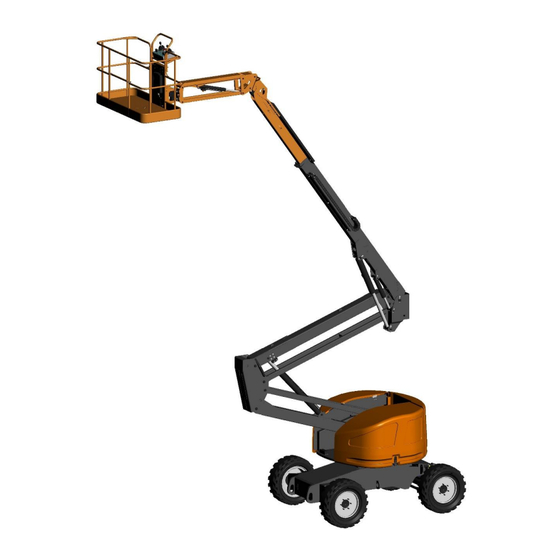
Page 11: General Description
( 6 ) 14. Work platform control station ( 3 ) 15. Manual storage box ( 7 ) ( 5 ) ( 15 ) ( 14 ) ( 1 ) ( 4 ) ( 2 ) Zebra 12 – Zebra 16 1NO0060EN-00... - Page 12 6. Hydraulic tank 7. Ground control station 8. Turret 9. Arm 1 10. Arm 2 11. Telescope 12. Arm 3 13. Rotator 14. Work platform 15. Work platform control station 16. Manual storage box Zebra 12 – Zebra 16 1NO0060EN-00...
-
Page 13: Characteristics - Dimensions
OPERATOR’S AND SAFETY HANDBOOK 1.2. CHARACTERISTICS - DIMENSIONS 1.2.1 Zebra 12 2100 2000 2780 5880 1990 1510 4500 2600 Zebra 12 – Zebra 16 1NO0060EN-00... - Page 14 OPERATOR’S AND SAFETY HANDBOOK 12.2m 10.2m 360° 4.3m Zebra 12 – Zebra 16 1NO0060EN-00...
- Page 15 OPERATOR’S AND SAFETY HANDBOOK 1.2.2. Zebra 16 2220 2100 2970 7090 90° 2190 1800 90° 5090 2220 Zebra 12 – Zebra 16 1NO0060EN-00...
- Page 16 OPERATOR’S AND SAFETY HANDBOOK 16.4m 14.4m 360° 180° 7.4m Zebra 12 – Zebra 16 1NO0060EN-00...
- Page 17 OPERATOR’S AND SAFETY HANDBOOK 1.2.3. Zebra 16 Stab 2220 2100 3820 7560 90° 2190 1800 90° 5560 2220 Zebra 12 – Zebra 16 1NO0060EN-00...
- Page 18 OPERATOR’S AND SAFETY HANDBOOK 8° (14% ) 11° (19% ) Zebra 12 – Zebra 16 1NO0060EN-00...
- Page 19 OPERATOR’S AND SAFETY HANDBOOK 16.8m 14.8m 360° 180° 7.8m Zebra 12 – Zebra 16 1NO0060EN-00...
- Page 20 The average maximum quadratic value weighted by the acceleration frequency to which the whole body is exposed does not exceed 0.5m/s². Due to constant improvements made to its products, ATN reserves the right to alter their specifications and equipment without notice.
- Page 21 Rotation (end to end) 15 à 20 seconds 15 to 20 seconds Note: The movement speeds may vary according to the telescope position, the adjustment of the limit switches and the adjustment of the load holding valves. Zebra 12 – Zebra 16 1NO0060EN-00...
-
Page 22: Safety Instructions
(Classification: Group B – Type 3). • Sufficient knowledge of how the machine operates to be able to recognise incorrect operation, a fault, or a risk of a fault. Zebra 12 – Zebra 16 1NO0060EN-00... -
Page 23: Tipping Hazards
• Keep the machine a good distance from holes, bumps, tilt, debris, and coatings likely to hide holes or other dangers on the ground. • Do not raise the work platform if the wind speed exceeds 12.5m/s (45km/h). Zebra 12 – Zebra 16 1NO0060EN-00... -
Page 24: Crushing And Collision Hazards
• Ask a person on the ground to guide you when visibility is reduced. Zebra 12 – Zebra 16 1NO0060EN-00... -
Page 25: Electrocution Hazards
NEAR ELECTRIC LINES OR POWERED EQUIPMENT. IN THE EVENT OF CONTACT WITH AN ELECTRIC LINE OR POWERED APPLIANCE, PERSONNEL ON THE GROUND MUST KEEP AWAY FROM THE MACHINE UNTIL THE ELECTRIC POWER IS CUT OFF. Zebra 12 – Zebra 16 1NO0060EN-00... -
Page 26: Falling Hazards
Avoid any projection on/to the machine, particularly to the fuel tank. • DO NOT use the machine in presence of electromagnetic fields (radar, high voltage currents…). This could damage the machine’s electronic components Zebra 12 – Zebra 16 1NO0060EN-00... -
Page 27: Operating Limits
• Disconnect the battery when working on the machine's electrical circuit or during welding operations. • Do not smoke, approach bare flames, or create sparks near the battery. • Do not place any metal tools or objects on the battery terminals. Zebra 12 – Zebra 16 1NO0060EN-00... - Page 28 • No modifications may be made to this machine without written agreement from the manufacturer ( ). These modifications will invalidate the warranty and the owner and/or user will be held responsible if an accident occurs. Zebra 12 – Zebra 16 1NO0060EN-00...
-
Page 29: Preparation And Inspection
4- Steering cylinder - Steering bar. 5- Front wheel motors - Wheel pivot axes: No screws missing - Screws correctly tightened. 6- Wheels Tyres in good condition – No wheel nuts missing – Wheels correctly tightened (see section 8.4) Zebra 12 – Zebra 16 1NO0060EN-00... - Page 30 ( 15 ) ( 12 ) ( 1 ) ( 2 ) ( 2 ) ( 3 ) ( 5 ) ( 6 ) ( 14 ) ( 13 ) ( 6 ) ( 4 ) Zebra 12 – Zebra 16 1NO0060EN-00...
- Page 31 ( 11 ) ( 12 ) ( 12 ) ( 11 ) ( 12 ) ( 12 ) ( 11 ) ( 12 ) ( 8 ) ( 10 ) ( 8 ) ( 9 ) Zebra 12 – Zebra 16 1NO0060EN-00...
- Page 32 OPERATOR’S AND SAFETY HANDBOOK Zebra 16 – Zebra 16 Stab (1) (2) (14) (15) (5) (6) (14) (10) (13) (1) (2) (14) (15) (14) (5) (6) (10) (13) Zebra 12 – Zebra 16 1NO0060EN-00...
- Page 33 OPERATOR’S AND SAFETY HANDBOOK (12) (11) (12) (13) (11) (11) (12) (12) (11) Zebra 12 – Zebra 16 1NO0060EN-00...
-
Page 34: Operating Checks
8- Drive the machine in slow speed: the axle should unlock, and the right-hand side wheel should contact the ground. 9- Repeat the previous procedure placing the wedge under the front left hand side wheel. Zebra 12 – Zebra 16 1NO0060EN-00... - Page 35 4- Fold arm 1 and raise arm 2 for about 1 meter and drive. 5- The machine must drive automatically in low speed. 6- Fold arm 2 and telescope out for about 30 centimeters and drive. 7- The machine must drive automatically in low speed. Zebra 12 – Zebra 16 1NO0060EN-00...
-
Page 36: Controls And Indicators
Read the safety instructions in Section 2 of this manual before using the machine. CONTROLS AND INDICATORS 4.1.1. GROUND CONTROL STATION Zebra 12 (10) (12) (11) (13) Zebra 12 – Zebra 16 1NO0060EN-00... - Page 37 12- Indicator lights. 13- Hourmeter. 1- Battery Master Switch: Cuts the starter battery of the machine’s electric circuit. Place the handle in horizontal position to switch on. Place the handle vertically to cut the supply. Zebra 12 – Zebra 16 1NO0060EN-00...
- Page 38 Tilt the switch in the direction of the arrow corresponding to the desired movement. Refer to Section 4.4.3 –Telescope. 9- Arm 3 Up / Down control: Tilt the switch in the direction of the arrow corresponding to the desired movement. Refer to Section 4.4.2 – Elevation. Zebra 12 – Zebra 16 1NO0060EN-00...
- Page 39 This light comes on during the preheating phase and goes off once the engine starts. Refer to Section 4.2 – Combustion engine operation. 13- Hourmeter: Indicates the global operating time of the combustion engine. Zebra 12 – Zebra 16 1NO0060EN-00...
- Page 40 14- Generator light and On/Off Switch (Option) 15- Overload Indicator Light. 16- Tilt Indicator Light. 17- Maintenance / System fault Indicator Light. 18- Control validation Indicator light. 19- Combustion engine Preheating Indicator light 20- Engine fault Indicator light. Zebra 12 – Zebra 16 1NO0060EN-00...
- Page 41 Refer to Section 4.4.6 – Work platform Rotation. 7- Platform Up / Down levelling Control: Tilt the switch forward to adjust the platform’s level up or rearwards to adjust the platform’s level down. Refer to Section 4.4.4 – Platform levelling. Zebra 12 – Zebra 16 1NO0060EN-00...
- Page 42 The light switches on when the structure is turned beyond the rear axle. The validation switch must be used before a drive movement is controlled. 2 sec Refer to Section 4.3 – Driving / Steering. Zebra 12 – Zebra 16 1NO0060EN-00...
- Page 43 • When the alternator is faulty: the alternator no longer charges the battery correctly. • When the diesel engine oil pressure is abnormally low or when the cooling fluid temperature is abnormally high: CUT the diesel engine as quickly as possible. Zebra 12 – Zebra 16 1NO0060EN-00...
- Page 44 IF THIS INDICATOR LIGHTS UP AND AN ALARM SOUNDS WHEN THE PLATFORM IS RAISED, IMMEDIATELY LOWER THE PLATFORM. 26- Outrigger ground contact indicator (Z16 Stab only) : The indicators are lit when the corresponding outriggers contact the ground. Zebra 12 – Zebra 16 1NO0060EN-00...
-
Page 45: Combustion Engine Operation
- NOTE- The engine can only be started if all the controls are in neutral and the enable pedal is released. Zebra 12 – Zebra 16 1NO0060EN-00... - Page 46 Refer to Section 9 – Control Screen. When the STOP & START device has stopped the engine, the indicator lights up on the platform control station. To start again, activate the engine start lever. Zebra 12 – Zebra 16 1NO0060EN-00...
- Page 47 The auxiliary hydraulic power unit can also be used to lower the platform. When an alternator operating fault is detected: ➢ The engine fault indicator lights up steady. The exact nature of the fault is indicated on the control screen. Zebra 12 – Zebra 16 1NO0060EN-00...
-
Page 48: Drive - Steering
Depress the right button to steer the wheels to the right or the left button to steer the wheels to the left. The wheels remain in the position they are in when the button is released. To bring the wheels back in line, use the opposite button. Zebra 12 – Zebra 16 1NO0060EN-00... -
Page 49: Elevating Structure
• From the work platform control station 1- Select the engine speed desired. 2- Depress the enable pedal. 3- Within 5 seconds, tilt the telescope control lever backwards to extend the telescope and forward to retract the telescope. Zebra 12 – Zebra 16 1NO0060EN-00... - Page 50 1- Press and hold down the enable button. The enable button must be depressed before a movement is controlled. 2- Tilt the platform rotation lever in the direction of the desired movement. 3- To stop the movement, release the control lever or the enable button. Zebra 12 – Zebra 16 1NO0060EN-00...
-
Page 51: Outriggers
3- Keep the lever tilted until: ➢ The red outrigger position indicator switches off. ➢ An acoustic signal sounds (4 quick beeps). ➢ The engine speed slows down. The outrigger movement stops automatically once they are fully retracted. Zebra 12 – Zebra 16 1NO0060EN-00... -
Page 52: Generator (Option)
DO NOT EXPOSE THE ONBOARD GENERATOR generator type installed. Refer to the TO DIRECT CONTACT WITH A WATER JET OR data plate on the generator. HIGH-PRESSURE CLEANER. Zebra 12 – Zebra 16 1NO0060EN-00... -
Page 53: Parking - Storage
• Protect the control stations if necessary as well as the instruction or warning stickers using covers. • For extended storage: - Disconnect the battery and charge if necessary. See Section 7-5 Battery. - Chock the machine's wheels. Zebra 12 – Zebra 16 1NO0060EN-00... - Page 54 OPERATOR’S AND SAFETY HANDBOOK • For storage, the overall length can be reduced by bringing the work platform under the telescopic arm (Zebra 12) on the side of the arms (Zebra 16) : Zebra 12: 1- Remove all material that may be in the work platform.
- Page 55 OPERATOR’S AND SAFETY HANDBOOK 4- Use the platform levelling control to fold it alongside the arms. 5- Lower arm 1 Zebra 12 – Zebra 16 1NO0060EN-00...
-
Page 56: Handling - Stowage For Transport
CHECK THAT THE PIVOTING MOTOR in parking-storage position as described in SUPPORT IS CORRECTLY LOCKED IN Section 4.7. PLACE. WHEN HANDLING MACHINE, THERE MUST BE NO PERSONNEL OR MATERIAL ON THE WORK PLATFORM. ARRIMAGE POUR LE TRANSPORT Zebra 12 – Zebra 16 1NO0060EN-00... - Page 57 • The machine must be in transport position. • The machine must be solidly secured to the vehicle platform as shown below. Use chains or slings rather than textile straps. In addition, the wheels may be chocked. Zebra 12 – Zebra 16 1NO0060EN-00...
-
Page 58: Regulations
- Before using the machine, never forget to check the machine suits to the workplace. This verification must be done by the user of the machine. PERIODIC INSPECTION - Every 6 months, the machine must be check by an approved agency. Zebra 12 – Zebra 16 1NO0060EN-00... -
Page 59: Safety Systems
Structure movement speed reduction. Telescope extension cut-out. Elevation movement for arms 1 and 2 cut-out. Arm 2 lowering movement and structure rotation movement cut-out until the telescope is not fully retracted. Combined movements prohibited. Zebra 12 – Zebra 16 1NO0060EN-00... -
Page 60: Load Control
An optional flashing light may be fitted to the machine. This equipment may be activated: On power up When the combustion engine is running During drive movements During drive and elevating structure movements. Refer to Section 9 – Control screen. Zebra 12 – Zebra 16 1NO0060EN-00... -
Page 61: Anti Crush Bar (Optional)
To restore machine operation, the anti-crush bar must be released, the controls returned to neutral and the enable pedal released. The priority ground control station remains operational even if the anti-crush bar remains activated. Zebra 12 – Zebra 16 1NO0060EN-00... -
Page 62: Emergency Procedures
2- Use the controls to lower the platform. • From the work platform control station 1- Press on the enable pedal. 2- Keep the Start / Auxiliary Group button tilted downwards. 3- Use the controls to lower the platform. Zebra 12 – Zebra 16 1NO0060EN-00... -
Page 63: Overriding The Safety Devices
1- Open the left-hand side cover (ground control station side). 2- Position the control station selector on ground control station. 3- From the menu display, press the button Zebra 12 access the settings menu. Zebra 16 Zebra 12 – Zebra 16 1NO0060EN-00... -
Page 64: Emergency Towing
OPERATOR’S AND SAFETY HANDBOOK 4- The settings menu request a 4 digit PIN code (contact ATN for mor information) 5- Only after you have entered the PIN code, flip up the safety cover for the override switch, tilt and hold the lever upwards. -
Page 65: After An Incident
See section 3.3 Only raise the platform by a metre if all the damages have been repaired and if all the controls are operating correctly. If in doubt, contact your reseller or the manufacturer. Zebra 12 – Zebra 16 1NO0060EN-00... -
Page 66: Maintenance For The Operator
This type of lubricant RECOMMENDED enables the engine to start at temperatures as low as -15°C. Depending on the operating conditions of the machine, you may need to adapt the type of lubricant (See graph opposite). Zebra 12 – Zebra 16 1NO0060EN-00... -
Page 67: Lubrication
( 5 ) ( 14 ) ( 7 ) ( 6 ) ( 8 ) ( 12 ) ( 12 ) ( 14 ) ( 16 ) ( 1 ) ( 2 ) ( 18 ) Zebra 12 – Zebra 16 1NO0060EN-00... - Page 68 (12)(14) (14) (10) (19) (14) (19) (12) (14) (19) (12) (14) ( 16 ) (14) (12) ( 18 ) (12) (13) (14) (12) (12) (14) (12) (13) (1) (2) (7)(8) (11) (17) (16) (18) Zebra 12 – Zebra 16 1NO0060EN-00...
-
Page 69: Hoses
Each time you start working with the machine, you have to check hoses statement and their connections. Each hose with a leak, pinch, abrasion or in such of other wear has to be replaced. Zebra 12 – Zebra 16 1NO0060EN-00... -
Page 70: Wheels
1- Screw all the nuts on by hand. Do not lubricate the threads. 2- Tighten the nuts turn by turn, respecting the order and the tightening steps indicated below: Wheel torque step step step 100-120Nm 250-280Nm 350-400Nm Zebra 12 – Zebra 16 1NO0060EN-00... -
Page 71: Battery
1.20 Charge the battery if the battery voltage in open circuit is under 12.40 volts. 1.15 Check the electrolyte level and recharge the battery approximately every two months. 1.10 100% Discharge depth Zebra 12 – Zebra 16 1NO0060EN-00... -
Page 72: Control Screen
CONTROL SCREEN The machine is fitted with an onboard tactile screen used for adjustments / diagnostics. Page closing Info and contact ATN: by clicking on the logo, you will access the different contacts at ATN Model and S/N Date and time Safety indicators / Machine faults Zebra 12 –... - Page 73 Engine not started or fault (Oil pressure, cooling fluid temperature > 110° or Alternator – voltage < 11.5V and engine started) Engine started without active fault Battery voltage: Battery voltage value (on the module MC43FS terminals) Battery voltage > 13.2V Zebra 12 – Zebra 16 1NO0060EN-00...
- Page 74 Clicking on one of the control stations gives access to the conditions of all inputs/outputs of the control station (buttons, joysticks, indicators). Input/output name Enty current SW = Switch True : active (button) False : non active Zebra 12 – Zebra 16 1NO0060EN-00...
- Page 75 8B : Revision / Diagnostic Menu 8C : Engine /Drive Menu 8D : Upper Station Control Menu 8E : Lower Station Control Menu 8F : Return to previous page 8G : Outrigger Menu (Zebra 16 Stabs only) Zebra 12 – Zebra 16 1NO0060EN-00...
- Page 76 : System : Measure : Adjust : Preferences Click on the « System » menu to get to the module conditions and system information: Info : gives the software’s name, version and machine’s serial number Zebra 12 – Zebra 16 1NO0060EN-00...
- Page 77 Errors recorded on the MC43FS Errors recorded on the MD4 Machine Event Overload with date and time: Machine Event tilt in elevated position with date and time Event Tilt reset done with date and time Zebra 12 – Zebra 16 1NO0060EN-00...
- Page 78 OPERATOR’S AND SAFETY HANDBOOK Click on the menu « Measure » to access measures of inputs/outputs: Zebra 12 – Zebra 16 1NO0060EN-00...
- Page 79 Speed reductions: access to speed reduction of the elevation movements for combined movements. Service: access to various internal parameters (preheat duration, detection engine started) Example of speed adjustment for arm 1 elevation: Speed adjustment Validation / Cancellation Return to default setting Zebra 12 – Zebra 16 1NO0060EN-00...
- Page 80 Click on the menu « Preferences » to access the screen’s settings: Contrast, date, language choice… Contrast and screen saving adjustment Date and time adjustment Language choice Menu Service / Diagnostic: Reserved for ATN (access with PIN code) Zebra 12 – Zebra 16 1NO0060EN-00...
- Page 81 Protection by PIN code Allows the hourmeter to be set (in the event the module was replaced): makes the parameter visible in Settings/Service Validates the service interval and / or hourmeter setting adjustment. Zebra 12 – Zebra 16 1NO0060EN-00...
- Page 82 Large displacement – Low and slope speed Small displacement – High speed Active brake: light off if unlocked Piloting Forward / reverse drive and right / left steering. The arrows lit indicate the movement in progress (Coil piloting). Zebra 12 – Zebra 16 1NO0060EN-00...
- Page 83 Info Engine start upper or lower control station, lit if active. Generator (option), lit if active. Tilt, lit in green if ok and in red if beyond. Overload, lit red if active. Zebra 12 – Zebra 16 1NO0060EN-00...
- Page 84 The green arrow on the movement indicate the active output (coil piloting). The gauge in percentage indicates the speed of the movement in progress (adjustment of the proportional from the screen).). The 4 arrows indicate the joystick active input with its tilt percentage (joystick action). Zebra 12 – Zebra 16 1NO0060EN-00...
- Page 85 Info elevation speed selector (Engine high or low speed). Info engine running (sensor RPM info). Info auxiliary group active (output). Generator (option), lit if active. Tilt, lit green if ok and red if beyond or disconnected. Overload, lit red if active. Zebra 12 – Zebra 16 1NO0060EN-00...
- Page 86 The green arrow on the movement indicate the active output (coil piloting). The gauge in percentage indicates the speed of the movement in progress (adjustment of the proportional from the screen). The green arrows around the button indicate the active input (button action). Zebra 12 – Zebra 16 1NO0060EN-00...
- Page 87 When the machine is lowered, the 3 indicators must be lit in green. Info Engine start button. Info enable button lower control box. Info engine running (sensor RPM info). Tilt, lit green if ok and red if beyond or disconnected. Overload, lit red if active. Zebra 12 – Zebra 16 1NO0060EN-00...
- Page 88 Note : when the 4 outriggers are fully retracted, the outrigger condition indicators are all off. The arrow indicates the operating direction of the outrigger (piloting of the solenoid elevation / descent). Zebra 12 – Zebra 16 1NO0060EN-00...
- Page 89 Pressure in the circuit of the outrigger movement piloting block in bars. Tilt, lit green if ok and red if beyond. Note : When the machine is on outriggers, chassis max tilt authorised is 1°. Zebra 12 – Zebra 16 1NO0060EN-00...
-
Page 90: Schematics
OPERATOR’S AND SAFETY HANDBOOK 10.1 ELECTRIC SCHEMATIC ZEBRA 12 Zebra 12 – Zebra 16 1NO0060EN-00... - Page 91 OPERATOR’S AND SAFETY HANDBOOK Zebra 12 – Zebra 16 1NO0060EN-00...
- Page 92 OPERATOR’S AND SAFETY HANDBOOK Zebra 12 – Zebra 16 1NO0060EN-00...
- Page 93 OPERATOR’S AND SAFETY HANDBOOK Zebra 12 – Zebra 16 1NO0060EN-00...
-
Page 94: Electric Schematic Zebra16 - Zebra 16 Stab
OPERATOR’S AND SAFETY HANDBOOK 10.2 ELECTRIC SCHEMATIC ZEBRA16 – ZEBRA 16 STAB Zebra 12 – Zebra 16 1NO0060EN-00... - Page 95 OPERATOR’S AND SAFETY HANDBOOK Zebra 12 – Zebra 16 1NO0060EN-00...
- Page 96 OPERATOR’S AND SAFETY HANDBOOK Zebra 12 – Zebra 16 1NO0060EN-00...
- Page 97 OPERATOR’S AND SAFETY HANDBOOK Zebra 12 – Zebra 16 1NO0060EN-00...
- Page 98 OPERATOR’S AND SAFETY HANDBOOK Zebra 12 – Zebra 16 1NO0060EN-00...
-
Page 99: Hydraulic Schematic Zebra 12
OPERATOR’S AND SAFETY HANDBOOK 10.3 HYDRAULIC SCHEMATIC ZEBRA 12 Zebra 12 – Zebra 16 1NO0060EN-00... - Page 100 OPERATOR’S AND SAFETY HANDBOOK Zebra 12 – Zebra 16 1NO0060EN-00...
-
Page 101: Hydraulic Schematic Zebra 16 - Zebra 16 Stab
OPERATOR’S AND SAFETY HANDBOOK 10.4 HYDRAULIC SCHEMATIC ZEBRA 16 – ZEBRA 16 STAB Zebra 12 – Zebra 16 1NO0060EN-00... - Page 102 OPERATOR’S AND SAFETY HANDBOOK Zebra 12 – Zebra 16 1NO0060EN-00...
- Page 103 OPERATOR’S AND SAFETY HANDBOOK Zebra 12 – Zebra 16 1NO0060EN-00...
-
Page 104: Z12 Stickers
OPERATOR’S AND SAFETY HANDBOOK 10.5 Z12 STICKERS 1AU0100 1AU0115 1AU0162 1AU0164 1090 1AU0102 Zebra 12 – Zebra 16 1NO0060EN-00... - Page 105 OPERATOR’S AND SAFETY HANDBOOK Repère Image Désignation Référence Qté Z12 Lower control box 1AU0349 Safety override 1AU0336 Circuit breaker 1AU0335 Zebra 12 – Zebra 16 1NO0060EN-00...
- Page 106 Forward arrow sticker 1AU0063-01 Backward arrow sticker 1AU0064 Marking tape yellow/black DATN054 11.4m Warm surface 1AU0188 Engine hazards 1AU0119 Z12 Platform control box 1AU0344-01 Z12 Platform control box 1AU0345-01 Z12 using limitations 1AU0097 User manual 1AU0105 Zebra 12 – Zebra 16 1NO0060EN-00...
- Page 107 OPERATOR’S AND SAFETY HANDBOOK 98 dB acoustic power 1AU0216 Z12 firm plate 1AU0215 Safety harness attachment 1AU0114 Stowing – lifting point 1AU0101 Wheel load 1AU0213 Fuel 1AU0100 Explosion hazard 1AU0115 Hydraulic oil 1AU0068 Zebra 12 – Zebra 16 1NO0060EN-00...
-
Page 108: Z16 Stickers
OPERATOR’S AND SAFETY HANDBOOK 10.6 Z16 STICKERS Zebra 12 – Zebra 16 1NO0060EN-00... - Page 109 OPERATOR’S AND SAFETY HANDBOOK Repère Image Désignation Référence Qté Z16 Lower control box 1AU0343 Safety override 1AU0336 Circuit breaker 1AU0335 Zebra 12 – Zebra 16 1NO0060EN-00...
- Page 110 Forward arrow sticker 1AU0063-01 Backward arrow sticker 1AU0064 Marking tape yellow/black DATN054 11.4m Warm surface 1AU0188 Engine hazards 1AU0119 Z16 Platform control box 1AU0344-01 Z16 Platform control box 1AU0345-01 Z16 using limitations 1AU0158 Zebra 12 – Zebra 16 1NO0060EN-00...
- Page 111 Stowing – lifting point 1AU0101 Wheel load 1AU0157 Fuel 1AU0100 Explosion hazard 1AU0115 Hydraulic oil 1AU0068 Outrigger hazard 1AU0245 (only Z16 STAB) Outrigger load 1AU0246 (only Z16 STAB) Turret alignment 1AU0278 (only Z16 STAB) Zebra 12 – Zebra 16 1NO0060EN-00...
- Page 112 OPERATOR’S AND SAFETY HANDBOOK NOTES Zebra 12 – Zebra 16 1NO0060EN-00...
Need help?
Do you have a question about the Zebra 12 and is the answer not in the manual?
Questions and answers