
Related Manuals for Pop PNT800L-PC


Summary of Contents for Pop PNT800L-PC
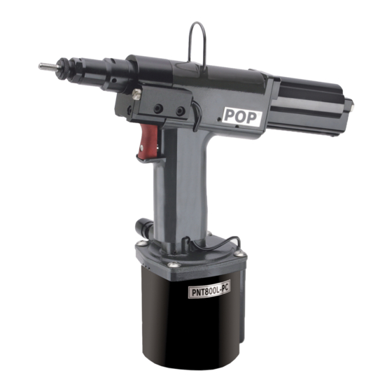
- Page 1 POP NUT ™ Tool PNT800L-PC Maintenance Manual Shanghai Huiyu Electronics Technology Co., Ltd. Tel:+86-21-54721680 Fax:+86-21-54721681 Web: www.huiyutools.cn...
-
Page 2: Table Of Contents
Setting Force Valve Spring Selection ....................15 Tool Operation ............................16 Setting Force Adjustment ........................18 Adjustment for Standard POP NUTs™....................18 Adjustment for ST & Thin Wall POP NUTs™ ..................19 Adjustment of Setting Force........................19 Maintenance............................21 Clean & Lube Mandrel ........................21 Lubricate Rotating Parts ........................21 Recharging Hydraulics........................22... -
Page 3: Introduction
Proper set achieved even with a small gap between the nut flange and Nosepiece. Table 1 lists the POP NUT™ blind rivet nuts that can be fastened using this tool. The Nosepiece and Mandrel must be changed to fit some sizes of POP NUT™. (See Table 5, Mandrel and Nosepiece Requirements table in the Specification section) Table 1: POP NUT™... -
Page 4: Safety Instructions
Safety Instructions TO INSURE PROPER FUNCTIONING AND SAFE OPERATION READ THIS MANUAL CAREFULLY BEFORE SETTING UP OR OPERATING THE POP NUT SERIES TOOLS DEFINITIONS: • CAUTION! – Failure to observe this precaution could result in physical damage or minor injury. -
Page 5: Specifications
0.5 - 0.6MPa (5 - 6 bar) (72.5 - 87 psi) Hydraulic Oil See Table 3, Specified Hydraulic Oils Setting capacity See Table 1, POP NUT™ blind rivet nut range = 72.7 dB(A), L = 77.6 dB(A), Aeq,T Tool Noise Level = 106.3 dB(C) -
Page 6: Tool Parts
(Not Included) Chamber Figure 2: Tool Parts Diagram Packaged Accessories Table 4: Packaged Accessories Part No. Item PNT800L-PC-T PNT800L-PC POP NUT™ Tool PNT600-132 Hook PNT600-133 Hex wrench 1.5 mm DPN907-006 Cap screw M4 X 20 DPN277-179 POP NUT™ Mandrel Release... - Page 7 Table 5: Mandrel and Nosepiece requirements Flat Nosepiece Mandrel Thick Wall I.D. M8X1.0 Thread size (Std & ST) POP NUT Thread size Part No. I.D. Part No. Thread size M4X0.7 PNT600-02-4 φ4.5 PNT600-01-4 M4X0.7 M5X0.8 PNT600-02-5 φ5.1 PNT600-01-5P M5X0.8 M6X1.0 PNT600-02-6 φ6.1...
-
Page 8: Pnt800L-Pc Diagram
PNT800L-PC Diagram Shanghai Huiyu Electronics Technology Co., Ltd. Tel:+86-21-54721680 Fax:+86-21-54721681 Web: www.huiyutools.cn... - Page 9 Shanghai Huiyu Electronics Technology Co., Ltd. Tel:+86-21-54721680 Fax:+86-21-54721681 Web: www.huiyutools.cn...
-
Page 10: Parts List
Parts List Item Part No. Description Item Part No. Description PNT600-01-6P Mandrel PNT600-039 Truss Head Screw DPN277-183 Chamber PNT600-02-6 Nose Piece PNT600-03 Lock Nut PNT600-41A R Joint Adapter PNT600-04A Nose Housing DPN900-021 O-Ring DPN277-001 Spin Pull Head Case PNT600-43 R Joint Spacer DPN277-002 Spin Pull Head PNT600-44B... - Page 11 PNT600-02-5 Nose Piece, M5 PNT600-101A Motor Case End Plate PNT600-02-8 Nose Piece, M8 DPN900-043 O-Ring DPN277-179 POP NUT Mandrel Release PNT600-103 M Valve Rod PNT600-104 Motor Case End *See table 5 for additional Mandrels and Nosepieces PNT600-105 Washer DPN900-044 O-Ring...
-
Page 12: Tool Setup
Tool Setup Initial Setup 1. Check that the correct Nosepiece and Mandrel are fitted for the POP NUT™. See the Basic Tool Operation section for proper tool adjustment. 2. Connect an air fitting to the Swivel Air Fitting of the tool. The Swivel Air Fitting is a 1/4 NPT thread. -
Page 13: Mandrel And Nosepiece Installation
3. Remove the Nosepiece from the tool by loosening the Lock Nut and unscrewing it (Figure 4). 4. Insert the POP NUT™ Mandrel Release tool over the Mandrel and into the Nose Housing. 5. Push Mandrel Release into the tool in order to disengage the Lock Pin Holder from the Mandrel. -
Page 14: Basic Tool Operation
Mandrel & Nosepiece Adjustment 1. Verify that the correct Mandrel and Nosepiece are fitted to the tool for the desired POP NUT™ (See Mandrel and Nosepiece Requirements table in the Specifications section). -
Page 15: Setting Force Valve Spring Selection
Setting Force Valve Spring Selection • There are two types of springs used with the PNT800L-PC tool • Spring selection depends on the insert being used. • Review the table below and select the proper Valve Spring for the insert being used. -
Page 16: Tool Operation
Figure 9: Loading the POP NUT™ onto tool Installing the POP NUT™ into the work piece 1. With the POP NUT™ mounted on the Mandrel, insert it perpendicularly into the hole of the work piece 2. Pull trigger and hold it in order to install the insert 3. - Page 17 Not OK Not OK Figure 11: Proper insertion of POP NUT™ threaded inserts into an application *Disengaging the tool from the insert WARNING! If you let go of the trigger during the installation sequence, the insert may not set completely, the hydraulics will reset and the tool will not automatically unthread from the insert.
-
Page 18: Setting Force Adjustment
Adjust the setting force of the tool according to insert size and thickness of work piece as indicated in the instructions below. • Test 5 pieces before beginning production work to ensure proper setting of the POP NUT™. • Proper setting force is critical:... -
Page 19: Adjustment For St & Thin Wall Pop Nuts
Use the following procedure to determine the proper setting requirements for the ST, TK, TL, TH Series of POP NUTs™: 1. Determine the Installed Length, “IL” of the POP NUT™ being used. This information can be found in the Emhart POP NUT™ Blind Rivet Nut catalog. - Page 20 MPa (15 psi)] • Multiple work piece thicknesses When using the POP NUT™ tool to set the same insert in multiple work piece thicknesses, adjust the setting force to accommodate the thinnest work piece. WARNING! Adjust Fastening Load Control Valve by 1/4 rotations.
-
Page 21: Maintenance
Over time, debris can stick to the Mandrel reducing its lubrication making it difficult to mount POP NUTs™ or causing premature wear or jams. Lube the Mandrel with 1 drop of oil. Use the same oil that is used with the Air Lubricator or an ISO VG 32 type oil. -
Page 22: Recharging Hydraulics
Recharging Hydraulics • If the stroke gets too short and the tool is unable to properly set an insert the Hydraulic Oil may need to be recharged. Note: If the stroke is still inadequate after recharging, the Hydraulic Seals may need to be replaced. - Page 23 Air Piston Tube Insertion Assembly Hole Air Piston Assembly Tube Handle Lower Tube Insertion Hole Tube Figure 19: Recharging and purging air bubbles 11. After replacement of the hydraulic oil, line up the Air Piston Assembly and the Tube Insertion Hole in the Handle Lower and push the Tube into place.
-
Page 24: Troubleshooting
Action Section Cannot thread the Incorrect Mandrel and Change to the correct parts Specifications, POP NUT™ onto Nosepiece for the POP Nut you are Table 5 Mandrel using. Mandrel threads are Replace the Mandrel Tool Setup damaged. Metal chip are jammed in... - Page 25 Mandrel rotates M-Valve Rod (#103) at back Remove Rear Case (#45) and PNT800L-PC clockwise as soon of Air Motor is stuck inspect M Valve End (#98) and Diagram as air is supplied to...
Need help?
Do you have a question about the PNT800L-PC and is the answer not in the manual?
Questions and answers