
Subscribe to Our Youtube Channel
Related Manuals for Pop PRT5400


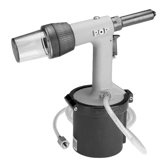
Summary of Contents for Pop PRT5400
- Page 1 5400 Series Rivet Tools PRT5400 / PRT5400LS / MCS5400 / MCS5400LS Operator and Maintenance Manual...
-
Page 2: Instruction Manual
INSTRUCTION MANUAL WARNING: SERVICE PROCEDURES SHOULD BE PERFORMED ONLY BY TRAINED SERVICE PERSONNEL. IMPORTANT READ THE FOLLOWING SAFETY INSTRUCTIONS CAREFULLY. DISCONNECT TOOL FROM AIR SUPPLY BEFORE ATTEMPTING SERVICE. SERVICE SHOULD ONLY BE PERFORMED BY TRAINED PERSONNEL. Page 2 EMHART TEKNOLOGIES • 50 Shelton Technology Center, Shelton, CT 06484 • Tel. (877) EMHART1 • Fax: (800) 225-5614 • www.emhart.com... -
Page 3: Safety Instructions
MCS5400LS Long stroke version with automatic vacuum mandrel collector attached. To determine model check length and height specifications or shipping carton label. Models PRT5400 and MCS5400 are shipped set up for 3/16" (4.8 mm) and smaller diameter rivets. A simple front end parts change is required to for setting larger diameter rivets. - Page 4 PACKED IN CARTON - MODELS PRT5400 and MCS5400 Part Number Part Name Data Model 5400 Rivet Tool Assembled with air line PRG540-56 Deflector Safety device - PRT5400 (LS) only MCS5400-8 Collector bottle MCS5400(LS) only PRT5500-8 Jaw Pusher 1/4" (6.4mm) diameter rivets...
-
Page 5: Specifications
SPECIFICATIONS PRT5400 MCS5400 Weight: 2.1 Kg (4.63 lbs.) 2.25 Kg (4.96 lbs.) Length: 296.75mm (11.68 in.) 322.10mm (12.66 in.) Height: 306.23mm (12.13 in.) 306.23mm (12.13 in.) Stroke: 18mm (.708 in.) 18mm (.708 in.) Pulling Force: 15.1 kN (3400 lbs.) 15.1 kN (3400 lbs.) Operating Pressure: 5.8 bar (85 psi.) -
Page 6: Preparation For Operation
2. To set up the tool for 1/4" (6.4mm) diameter open end rivets attach Nosepiece 12-D, install Jaws 3-B, and Jaw Pusher 22-B and remove Mandrel Guide Tube 71. Refer to SERVICE PROCEDURES. A wide variety of Nosepieces are available from your POP distributor for special rivets and special applications or to improve access problems. -
Page 7: Operation
5. Squeeze the trigger 13 to set the rivet. Once the rivet is set, release the trigger. If using a PRT5400 or PRT5400LS be sure to clear the mandrel from the tool by tipping the tool to let the mandrel slide either out the front or out the back of the tool. - Page 8 SERVICING THE JAWS, JAW PUSHER AND JAW PUSHER SPRING Regularly cleaning the Jaws and front end parts will prevent mandrels sticking in the Jaws and extend the life of the Jaws. 1. Disassemble the tool front end as described above. Clean Jaws 3 using a brush and solvent. If jaw teeth show significant wear replace both jaws.
-
Page 9: Service Notes
PRT5400, MCS5400, PRT5400LS, MCS5400LS DISASSEMBLY & ASSEMBLY INSTRUCTIONS IMPORTANT READ SAFETY INSTRUCTIONS ON PAGE 2 OF INSTRUCTION MANUAL. DISCONNECT TOOL FROM AIR SUPPLY BEFORE ATTEMPTING SERVICE. SERVICE SHOULD BE PERFORMED BY TRAINED PERSONNEL ONLY. SERVICE NOTES All disassembly procedures should be performed in a clean, well lighted work area. O-rings, seals and sealing surfaces should be lightly lubricated with a white mineral oil based grease such as Lubriplate 130-AA or equiv- alent prior to assembly. - Page 10 HANDLE CAP ASSEMBLY (PRT OPTION) Remove Deflector 47. Remove Handle Cap Screws 48. 3. Pull off Handle Cap 49. 4. Remove O-rings 8 and 35. ASSEMBLE IN REVERSE ORDER Assembly Notes: 1. Lubricate O-rings prior to installation. 2. Tighten Handle Cap Screws 48 to torque specification in Table 1.
- Page 11 PULLING HEAD ASSEMBLY (HYDRAULIC PISTON) 1. Remove Nose Housing 44 (steps 1-7 in the FRONT END ASSEMBLY section of this manual), Intensifier Chamber 45 and Intensifier Assembly 29 (steps 1-3 in the INTENSIFIER ASSEMBLY section of this manual). 2. Remove Handle Cap Assembly 49 (PRT Option - see HANDLE CAP ASSEMBLY section of this manual) or Mandrel Collection System Assembly (MCS Option - see MANDREL COLLECTION SYSTEM ASSEMBLY section of this manual).
- Page 12 RAM SLEEVE ASSEMBLY 1. Remove Intensifier Assembly 29 (steps 1-4 in the INTENSI- FIER ASSEMBLY section of this manual). 2. Drain hydraulic oil (step 3 in PULLING HEAD ASSEMBLY section of this manual). 3. Remove Retainer Plate Screws 1 and Lock Washers 9. 4.
- Page 13 AIR VALVE AND PRESSURE REGULATOR ASSEMBLY 1. Remove Trigger 13 by driving out Trigger Pin 14 using 2mm (0.080") pin punch. 2. Remove Ram Sleeve Retainer Plate 34 (steps 1-4 in RAM SLEEVE ASSEMBLY section of this manual). 3. Using the pin punch or a screwdriver through the Trigger opening gently push out the Pressure Regulator 39, the Air Valve Assembly 16, and the Valve Plug 15.
- Page 14 MANDREL COLLECTION SYSTEM ASSEMBLY (MCS OPTION) 1. Remove Collector 58 and Collector Gasket 55. 2. Remove Vacuum Cap Screws 65, Filter Cover 59 and Filter 61. 3. Pull the Entire MCS Assembly from the Handle 31. 4. Grasp the Switch Deflector Ring 67 and the Vacuum Cap Body Assembly 63 and twist to remove the Vacuum Cap Body Assembly.
- Page 15 HYDRAULIC FLUID CHARGING PROCEDURE IMPORTANT TOOL MUST BE DISCONNECTED FROM THE AIR SUPPLY. All procedures must be performed in a clean environment. Use only approved hydraulic fluids specified in this manual. Use hydraulic fluid that is clean and free from air bubbles. Take care to prevent foreign matter from entering the tool.
- Page 16 PROCEDURE 1. Loosen Fill Screw 10. 2. Place the tool upside down in a soft jawed vise. Grip the tool gently on the aluminum casting in the middle of the tool handle grip area. 3. Remove Clamp Screws 37 and 38, Clamp Nuts 23, Right Clamp 42 and Left Clamp 43. 4.
-
Page 17: Maintenance Schedule
MAINTENANCE SCHEDULE DAILY 1. Inspect tool and air supply hose for damage. Replace damaged parts immediately. 2. Purge air supply filters to eliminate accumulated dirt, oil and water. 3. Check to see that pressure regulator is properly set at 5 bar (85 psi). 4. - Page 18 INTENSIFIER CHAMBER SLEEVE (PRT/MCS5400LS) 22-A PRT5400-6 JAW PUSHER (1/8"-3/16", 3.2mm-4.8mm) PRT/MCS5400 22-B PRT5400-8 JAW PUSHER (1/4", 6.4mm) PRT/MCS5400LS PRG540-43 MANDREL GUIDE (Installed on PRT5400 & MCS5400) PRT5400-113 CLAMP NUT PRT5200-220* AIR LINE ASSEMBLY MCS OPTION PRT OPTION ITEM PART NO.
- Page 19 22-B 22-A 12-A 12-B PRT Option 12-C 12-D U . S . A . MCS Option Page 19 EMHART TEKNOLOGIES • 50 Shelton Technology Center, Shelton, CT 06484 • Tel. (877) EMHART1 • Fax: (800) 225-5614 • www.emhart.com...
- Page 20 AMERICAS EUROPE ASIA PACIFIC United States Denmark Japan Connecticut Farverland 1 B Shuwa Kioicho Park Building 3F 50 Shelton Technology Center DK-2600 Glostrup, Denmark 3-6 Kioicho, Chiyoda-Ku P .O. Box 859 Tel. +45 44 84 11 00 Tokyo 102-0094, Japan Shelton, CT 06484 USA Fax.+45 44 84 62 12 Tel.
Need help?
Do you have a question about the PRT5400 and is the answer not in the manual?
Questions and answers