
Related Manuals for Migomag MOMACDC


Summary of Contents for Migomag MOMACDC
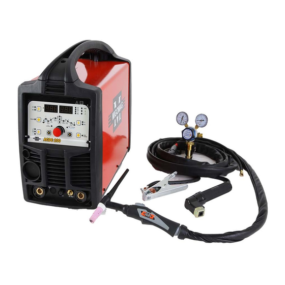
- Page 1 Operators Manual MIGOMAG ACDC 200 INVERTER Migomag ACDC 200 TIG Inverter Part Number: MOMACDC...
- Page 2 This Operating Manual has been designed to instruct you on the correct use and operation of your Migomag Welder. Your satisfaction with this product and its safe operation is our ultimate concern. Therefore please take the time to read the entire manual, especially the Safety Precautions.
-
Page 3: Table Of Contents
Table of Contents Section Page General Safety Rules Receiving Description Unpacking Specifications Know your Welder Front Control Panel Installation Operation Troubleshooting Chart Spare Part Diagram Spare Part List Maintenance, Transportation and Storage Hazard Warnings Warranty Terms & Conditions Migomag TIG Torch... -
Page 4: General Safety Rules
Operators Manual General Safety Rules WARNING: Read and understand all instructions. Failure to follow all instructions listed below may result in serious injury. CAUTION: Do not allow persons to operate or assemble this MOM ACDC 200 until they have read this manual and have developed a thorough understanding of how the MOM ACDC 200 works. - Page 5 • Fumes emitted from the welding process displace clean air and can result in injury or death • Do not breathe in fumes emitted by the welding process. Make sure your breathing air is clean and safe Model No MOMACDC...
- Page 6 Operators Manual • Work only in a well-ventilated area or use a ventilation device to remove welding fumes from the environment where you will be working • Do not weld on coated materials (galvanized, cadmium plated or containing zinc, mercury or barium). They will emit harmful fumes that are dangerous to breathe. If necessary use a ventilator, respirator with air supply or remove the coating from the material in the weld area •...
- Page 7 • Keep TIG gun and ground cables on the same side of your body Shielding Gas Cylinders can Explode WARNING! High pressure cylinders can explode if damaged, so treat them carefully. • Never expose cylinders to high heat, sparks, open flames, mechanical shocks or arcs Model No MOMACDC...
- Page 8 Operators Manual • Do not touch cylinder with TIG gun • Do not weld on the cylinder • Always secure cylinder upright to a cart or stationary object • Keep cylinders away from welding or electrical circuits. • Use the proper regulators, gas hose and fittings for the specific application •...
-
Page 9: Receiving
Check the equipment received against the shipping invoice to make sure the shipment is complete and undamaged. If any damage has occurred in transit, please immediately notify your supplier. The Migomag ACDC 200 TIG inverter package contains; • MIGOMAG ACDC 200 TIG Inverter Power Source • 4mt TIG torch MMPRO26FX4MT •... -
Page 10: Specifications
Operators Manual Specifications Fitted Supply Cable Manufactured to Australian Standard 2.5 mm2 Three Core, Heavy Duty PVC AS60974-1: 2006 AS610003.3 Cooling Fan cooled, air drawn in through front Primary Voltage grill. 240 Vac, 50/60 Hz Insulation Rated Primary Current (I eff) Class H, 150°C Rise 15 Amps Rods sizes... - Page 11 25-30 Stainless V groove >3.0-6.0 70-120 degrees Steel Positive 35-45 X groove >6.0-12 2.5-3.2 100-150 10-14 degrees Vertical 1-2.5 1.6-2.5 45-90 Pure Joint Aluminum Positive V groove 90-180 10-12 Alu-Mag degrees Alloy X groove 8-12 150-220 12-16 Model No MOMACDC...
-
Page 12: Know Your Welder
Operators Manual Know your Welder The MOM ACDC 200 is a digital model and can be used for MMA, ACTIG, DCTIG and PULSE TIG. The parameters can be preset and showed, welding current and voltage can real-time display, for easy operation. Factory standard: EN60974-1 STD Accessories: Tig torch and regulator 1. -
Page 13: Front Control Panel
8. Voltage display - To show the preset current when setting and the welding current when working. 9. Procedure parameter display - This part shows the procedure, when the indicator lights, the corresponding parameter can be adjusted with the adjustment knob. See following details: Model No MOMACDC... -
Page 14: Installation
Operators Manual Pre-flow Time indicator light Pulse frequency indicator light (PULSE) Hot start current indicator light (MMA) Background current indicator light (PULSE) Ignition current indicator light (4T) Minus grade time indicator light (4T) Up Slope time indicator light (4T) Arc stopping current indicator light (4T) Welding current indicator light (CC) Gas delay time indicator light Peak current indicator light (PULSE) - Page 15 Do not use an extension cord over 25 ft. in length. 3. MMA mode connection method TABLE 1. 4. TIG mode connection method 5. Foot control pedal Foot Control Model No MOMACDC...
-
Page 16: Operation
Operators Manual 6. Input connection method WARNING! EXPOSURE TO A WELDING ARC IS EXTREMELY HARMFUL TO THE EYES AND SKIN! Prolonged exposure to the welding arc can cause blindness and burns. Never strike an arc or begin welding until you are adequately protected. Wear flame-proof welding gloves, a heavy long sleeved shirt, trousers without cuffs, high topped shoes, and an ANSI approved welding helmet. - Page 17 Step 1: Use this adjustment to adjust the parameter selected on Step2 2. TIG: Step 3: Use this adjustment to adjust the parameter selected on Step2 Step 2: Press this knob to choose the parameter Step 1:Press this knob, choose Model No MOMACDC...
- Page 18 Operators Manual 2.1 DC TIG welding Set the (Welding mode knob) to “ HF ignition lift arc” and (AC/DC transfer knob) to DC“ ” , would enter into DC TIG welding mode. In this mode to adjust by “Parameter knob” ”Parameter positive knob”: ) to adjust the Pre-flow time ( Ic ) to adjust the welding current;...
- Page 19 NOTE: This Up Slope operates in (4T) TIG modes only and is used to set the time for the weld current to ramp up, after the torch trigger switch has been pressed then released, from Initial Current to High or BASE current. Model No MOMACDC...
- Page 20 Operators Manual 2.4 AC TIG welding Set (Welding mode knob) to “TIG HF ignition lift arc” and (AC/DC transfer knob) to “AC ” would enter into AC TIG welding mode. Then to choose by “Parameter knob” ”Parameter positive knob”: ) to adjust the Pre-flow time; (Ic) to adjust the welding current ) to adjust the stopping gas delay time;...
- Page 21 Lift the electrode away from the work piece by turning it so that gas nozzle rests against the work piece (2 ja 3), and the arc will ignite and the current will rise to the welding level within the up-slope time (4). Model No MOMACDC...
- Page 22 Operators Manual 3. Stick welding skill 3.1 Welding Positions There are two basic positions, for welding: Flat and Horizontal. Flat welding is generally easier, faster, and allows for better penetration. If possible, the work piece should be positioned so that the bead will run on a flat surface. 3.2 Preparing the Joint Before welding, the surface of work piece needs to be free of dirt, rust, scale, oil or paint or it will create brittle and porous welds.
- Page 23 It is best to practice your welds on scrap metal which matches the metal you intend to work with to determine correct heat setting and electrode choice. See the following helpful trouble shooting tips to determine if you are using a correct electrode. Model No MOMACDC...
- Page 24 Operators Manual 1. When proper rod is used: a. The bead will lay smoothly over the work without ragged edges b. The base metal puddle will be as deep as the bead that rises above it c. The welding operation will make a crackling sound similar to the sound of eggs frying 2.
- Page 25 To lay a weld bead, only 2 movements are required; downward (as the electrode is consumed) and in the direction the weld is to be laid, as in following figure: Model No MOMACDC...
- Page 26 Operators Manual 2.3 Types of Weld Bead The following paragraphs discuss the most commonly used arc welding beads. The stringer bead Formed by traveling with the electrode in a straight line while keeping the electrode centered over the weld joint. The weave bead Used when you want to deposit metal over a wider space than would be possible with a stringer bead.
- Page 27 The first attempts in practice will probably fall short of acceptable weld beads. Too long of an arc will be held or the travel speed will vary from slow to fast (see following) Model No MOMACDC...
- Page 28 Operators Manual A. Weld speed is too fast B. Weld speed is too slow C. Arc is too long D. Ideal weld A solid weld bead requires that the electrode be moved slowly and steadily along the weld seam. Moving the electrode rapidly or erratically will prevent proper fusion or create a lumpy, uneven bead.
- Page 29 Tungsten Electrode Current Ranges Electrode Diameter DC Current (Amps) (1.0mm) 30-60 (1.6mm) 60-115 (2.4mm) 100-165 (3.2mm) 135-200 (4.0mm) 190-280 (4.8mm) 250-340 * Note gas used for ACDC TIG welding use pure argon. Model No MOMACDC...
- Page 30 Operators Manual Guide for Selecting Filler Wire Diameter Filler Wire Diameter DC Current Range (Amps) (1.6mm) 20-90 (2.4mm) 65-115 (3.2mm) 100-165 (4.8mm) 200-350 Tungsten Electrode Types Electrode Type Welding Application Features Colour Code (Ground Finish) Thoriated 2% DC welding of mild Excellent arc stating, steel, stainless steel Long life, High...
- Page 31 TIG Welding is generally regarded as a specialised process that requires operator competency. While many of the principles outlined in the previous Arc Welding section are applicable a comprehensive outline of the TIG Welding process is outside the scope of this Operating Manual. Model No MOMACDC...
-
Page 32: Troubleshooting Chart
Operators Manual Troubleshooting Chart Breakdown Analysis Solutions Cooling fan isn’t Cooling fan broken Replace the fan working Cable broken/fallen Find the disconnected wire and connect reliability No high frequency Torch switch broken Replace the torch ignition Main PC board Replace the PC board broken Run-on plate Replace the run-on plate... - Page 33 Power trip First turning on Not fault, trip caused by the after power long charging filter capacitor in the time (2days more) main board, return on the power switch Others Please contact with the supplier/ manufacture Model No MOMACDC...
-
Page 34: Spare Part Diagram
Operators Manual Spare Part Diagram... -
Page 35: Spare Part List
2 pin panel mount trigger switch 85001026 Front Plastic cover panel 85001027 Earth lead complete 85001028 Tig torch complete 85001029 Potentiometer knob 85001030 Front panel board support plate 85001031 Front display control card 85001032 Panel mount dinse connector 85001033 Hall Model No MOMACDC... -
Page 36: Maintenance, Transportation And Storage
Operators Manual 85001034 Secondary rectifier heat sink 85001035 Fast recovery diode 85001036 Secondary rectifier heat sink 85001037 Secondary rectifier inverter board 85001038 Resistance 2 85001039 Resistance 1 85001040 Gun switch isolation plate 85001041 Board fixed plate 85001042 Bracket for current filter 85001043 Main PCB control card 85001044... -
Page 37: Warranty
• Replace the Product In the event of such a defect, the customer should return the Product to the original place of purchase, with proof of purchase, or contact Migomag on 03 9313 3100 to locate an authorised service agent. -
Page 38: Terms & Conditions
Operators Manual Terms & Conditions WARRANTY AND LIABILITY OF SELLER (a) The Seller makes no express warranties under this Agreement. Manufacturers of goods may, from time to time, provide a voluntary warranty directly to the Buyer in relation to goods supplied to the Buyer. The Buyer must address issues relating to a manufacturer’s warranty with the manufacturer on the terms of that warranty. - Page 39 For more Terms & Conditions please visit www.migomag.com.au. Warranty provided by: Migomag Welding Supplies...
-
Page 40: Migomag Tig Torch
Operators Manual Migomag TIG Torch MMPRO26FX Air Cooled Pro-Grip TIG Welding Torch Rating: 200A DC, 150A AC @ 60% Duty Cycle, EN60974-7 1.0mm-4.0mm Electrodes Torch Head Stock Code Model Description MMPRO26FX Torch Head Flexible Air Cooled 200A DC 4 MT... - Page 41 PROLC100 Knuckle Joint c/w Lock Nut PROLC100-08 Leather Cover x 0.8mt/2.6ft Complete Cover Assembly x 4mt/12.5ft PROCO100-40 Complete Cover Assembly x 8mt/25ft PROCO100-80 Neoprene Cover 3.2mt /10.5ft PRONC32 Neoprene Cover 7.2mt/23.6ft PRONC72 PROJK100 Sheath Jointing Repair Kit Model No MOMACDC...
- Page 42 Lareg Diameter Gas Lens Cup Stock Code Description 57N75 Large Dia Gas Lens Cup 10mm Bore 57N74 Large Dia Gas Lens Cup 13mm Bore 57N88 Large Dia Gas Lens Cup 16mm Bore 57N87 Large Dia Gas Lens Cup 19mm Bore Model No MOMACDC...
Need help?
Do you have a question about the MOMACDC and is the answer not in the manual?
Questions and answers