
Related Manuals for Migomag SIM 200 LCD


Summary of Contents for Migomag SIM 200 LCD
- Page 1 Operators Manual MIGOMAG SIM 200 LCD Multi Process 3 in 1 Welding Inverter with PFC (Internal Wirefeeder) Migomag SIM 200 LCD DC MIG DC, TIG / MMA Arc Welder Part Number: ASIM200LCD...
- Page 2 This Operating Manual has been designed to instruct you on the correct use and operation of your Migomag Welder. Your satisfaction with this product and its safe operation is our ultimate concern. Therefore please take the time to read the entire manual, especially the Safety Precautions.
-
Page 3: Table Of Contents
Recommended Welding Wires and Gas Mixes Installation Operation External Trouble Shooting Main Circuit Diagram Spare Part Diagram Drive Bracket Assembly Part Diagram Spare Part List Drive Bracket Assembly Part List Service, Maintenance, Transportation and Storage Warning Label Warranty Terms & Conditions Migomag MIG Torch... -
Page 4: General Safety Rules
Operators Manual General Safety Rules WARNING: Read and understand all instructions. Failure to follow all instructions listed below may result in serious injury. CAUTION: Do not allow persons to operate or assemble this SIM 200 until they have read this manual and have developed a thorough understanding of how the SIM 200 works. - Page 5 Migomag SIM 200 LCD • Follow the instructions in this manual • Keep welder in the off position when not in use • Connect ground lead as close to the area being welded as possible to ensure a good ground •...
- Page 6 Operators Manual • Use only recommended replacement cables and cords • Always attach ground clamp to the work piece or work table as close to the weld area as possible • Do not touch the welding wire and the ground or grounded work piece at the same time •...
- Page 7 Migomag SIM 200 LCD • Cover all bare skin areas exposed to the arc with protective clothing and shoes. Flame- retardant cloth or leather shirts, coats, pants or coveralls are available for protection • Use screens or other barriers to protect other people from the arc rays emitted from your welding •...
- Page 8 Operators Manual Sparks/Flying Debris CAUTION! Welding creates hot sparks that can cause injury. Chipping slag off welds creates flying debris. • Wear protective apparel at all times: ANSI-approved safety glasses or shield, welder’s hat and ear plugs to keep sparks out of ears and hair Electromagnetic Field - CAUTION! •...
- Page 9 • Store idle MOM SIM 200 LCD. When MOM SIM 200 LCD is not in use, store it in a secure place out of the reach of children. Inspect it for good working condition prior to...
-
Page 10: Description
Please retain these instructions for future reference. Description The SIM 200 LCD series is a DC inverter 3 in 1 MIG welder. This unit uses 1~Phase 240V, 50/60HZ AC power. A 25 amp time delay fuse or circuit breaker is recommended. The SIM 200 LCD series is ideal for light industrial. -
Page 11: Specifications
Migomag SIM 200 LCD Specifications Rating IP21S Manufactured to Australian Standard AS60974-1: 2006 Fitted Supply Cable AS610003.3 2.5 mm2 Three Core, Heavy Duty PVC Primary Voltage 240 Vac, 50/60 Hz Cooling Fan cooled, air drawn in through front of Rated Primary Current (I eff) -
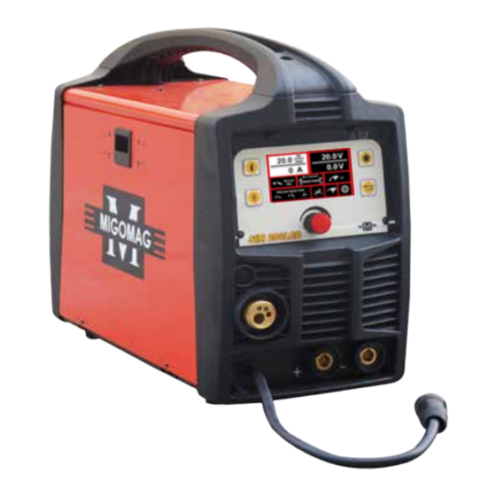
Page 12: Know Your Welder
Operators Manual Know your Welder Factory standard: EN60974-1 1. PRIMARY INPUT CABLE 2. ON/OFF - In the “OFF” position no power is being supplied. In the “ON” position power is supplied to the main transformer and control circuit 3. REGULATOR FLOW METER 4. - Page 13 Migomag SIM 200 LCD Front Control Panel 1. LCD: Shows all process from function selection to welding. 2. Gas-check button: press the button to check gas flow. 3. Wire-check button:press the button to feed wire. 4. Multi-function adjusting knob: For function selection; Press for confirming. Allows user to adjust the current and wire feeding speed accurately.
-
Page 14: Interface Description
Operators Manual Interface Description 1. Multi-function selection: Process Selection Mode DC MIG, DC TIG & MMA 2. Polarity setup: Shows connection for different welding polarity, for different processes. Gasless MIG... - Page 15 Migomag SIM 200 LCD DC TIG 3. Welding display: Shows all selected parameters. a. Under MIG welding Wire feed speed Amps when welding & after Set voltage Voltage after welding Arc control Trigger mode Welding process mode Settings Process selection...
- Page 16 Operators Manual b. TIG welding display, user can set current parameter. Amps Volts Settings Process selection c. Stick welding, user can set current to arc force parameter. Amps Volts Arc force & dynamics VRD mode Settings Process selection 4.Setting screen: It shows language, units, light setting, information and recover setting. Program version seriel number Language...
- Page 17 Migomag SIM 200 LCD 5. Alarm interface:It shows the machine is overloaded and the internal temperature is too high. Weld output will turn off automatically but the fan will still be working. When the internal temperature is decreased, the alarm interface will turn off and the machine will be ready to weld.
-
Page 18: Recommended Welding Wires And Gas Mixes
Operators Manual Recommended Welding Wires and Gas Mixes FE= Mild Steel Mig welding wire. The recommended wire grade is ER70S6 Kiswel KC 28 Mig wire. Mild steel Mig welding Gas recommendation for Fe/Mild steel is Coregas 5/2. The gas mix is 93% argon 5% Co2 and 2% O2. SS= Stainless Steel Mig welding wire. -
Page 19: Installation
Migomag SIM 200 LCD Installation 1. Power Requirement AC single phase 240V, 50/60HZ fused with a 25 amps time delayed fuse or 36 AMP circuit breaker is required. Check with local requirements for your situation. WARNING: • High voltage danger from power source! Consult a qualified electrician for proper installation of receptacle. - Page 20 Connection to Electrical Mains Power Supply The SIM 200 LCD is factory fitted with a 3 metre, 3 core 2.5mm2 Heavy Duty PVC mains power supply cable with moulded 3 pin, 15 Amp, Single Phase plug. A 15 Amp plug and socket is recognisable by a wide Earth pin. Power Supply authorities require that equipment fitted with a 15 Amp plug shall ONLY be connected to a 240 Volt, 15 Amp power point.
- Page 21 Migomag SIM 200 LCD The current rating of the mains cable depends on cable size and method of installation. Refer to AS/NZS 3008.1, Table 9. 4. Ground Clamp Connection Clear any dirt, rust, scale, oil or paint on the ground clamp. Make certain you have a good solid ground connection.
- Page 22 Operators Manual 2. Gasless MIG 3.MMA 4. DC TIG 6.2 The gas hose, regulator and gas cylinder connection Attach one end of the gas hose to the quick release fitting (gas inlet) located on the back panel of the welder. Attach the other end to the gas regulator which is attached to the shielding gas cylinder.
-
Page 23: Operation
Migomag SIM 200 LCD NOTE: Slowly open the cylinder valve by turning it counterclockwise until the cylinder pressure gauge registers on the first gauge of the regulator. Turn the adjustment knob clockwise (right) slowly to increase gas flow to 15 lpm. To reduce the gas flow turn the adjustment counterclockwise (left). - Page 24 Operators Manual 3. Position the Torch to the Work Piece There are two angles of the torch nozzle in relation to the work piece that must be considered when welding. 3.1. Angle A can be varied, but in most cases the optimum angle will be 60 degrees, the point at which the torch handle is parallel to the work piece.
- Page 25 Migomag SIM 200 LCD 5.3. Hold the torch in one hand, allowing the nozzle to rest on the edge of the work piece farthest away from you, and at an angle similar to that which will be used when welding.
- Page 26 Operators Manual Travel speed is the rate at which the torch is being pushed or pulled along the weld joint. For a fixed heat setting, the faster the travel speed, the lower the penetration and the lower and narrower the finished weld bead. Likewise, the slower the travel speed, the deeper the penetration and the higher and wider the finished weld bead.
- Page 27 Migomag SIM 200 LCD A good starting point for angle B is about 30 degrees DOWN from being perpendicular to the work piece. VERTICAL POSITION is easier for many people to Pull the torch from top to bottom. It can be difficult to prevent the puddle from running downward.
- Page 28 Operators Manual NOTE: WHEN USING SELF-SHIELDING FLUX-CORE WIRE it is very important to thoroughly chip and brush the slag off each completed weld bead before making another pass or the next pass will be of poor quality. Fillet Weld Joints. Most fillet weld joints, on metals of moderate to heavy thickness, will require multiple pass welds to produce strong joint.
- Page 29 Migomag SIM 200 LCD 1. The BURN-THROUGH METHOD welds two overlapped pieces of metal together by burning through the top piece and into the bottom piece. With the burn-through method, larger wire diameters tend to work better than smaller diameters. Wire diameters that tend to work best, with the burn-through method are 0.035 inch self-shielding flux-core...
- Page 30 Operators Manual 1. When proper rod is used: • The bead will lay smoothly over the work without ragged edges • The base metal puddle will be as deep as the bead that rises above it • The welding operation will make a crackling sound similar to the sound of eggs frying 2.
- Page 31 Migomag SIM 200 LCD 2. Welding Techniques The best way to teach yourself how to weld is with short periods of practice at regular intervals. All practice welds should be done on scrap metal that can be discarded. Do not attempt to make any repairs on valuable equipment until you have satisfied yourself that your practice welds are of good appearance and free of slag or gas inclusions.
- Page 32 Operators Manual 2.3 Types of weld bead The following paragraphs discuss the most commonly used arc welding beads. The stringer bead is formed by traveling with the electrode in a straight line while keeping it centered over the weld joint. The weave bead is used when you want to deposit metal over a wider space than would be possible with a stringer bead.
- Page 33 Migomag SIM 200 LCD 2.5 Judge a good weld bead When the trick of establishing and holding an arc has been learned, the next step is learning how to run a good bead. The first attempts in practice will probably fall short of acceptable weld beads.
-
Page 34: External Trouble Shooting
‘OVERLOAD’ light will be illuminated. The thermostat will reset automatically - do not switch the equipment off as the cooling fan will assist the resetting of the thermostat • If problem persists after the cool down period, call your Migomag service agent Power source has low weld output 1. - Page 35 Migomag SIM 200 LCD Constant poor arc characteristics Check that the: 1. Correct polarity has been selected for work and weld cables (refer page 10). 2. Shielding gas is correct for the consumable wire in use (refer page 12). 3. Welding circuit is making good electrical connection. Ensure that the work clamp is securely tightened onto the work piece so that good electrical contact is achieved 4.
-
Page 36: Main Circuit Diagram
Operators Manual Main Circuit Diagram... -
Page 37: Spare Part Diagram
Migomag SIM 200 LCD Spare Part Diagram Model No ASIM200LCD... -
Page 38: Drive Bracket Assembly Part Diagram
Operators Manual Drive Bracket Assembly Part Diagram * See Page 33 Migomag Machine Solid Wire V-Grooved Number Sim 200-Sim 250- Sim 350 and Sim PF4 0.6-0.8mm 0.9-1.0mm 1.0-1.2mm 1.2-1.6mm Part Number 87003100 87003101 87003102 87003103 Gasless Wire Flux Cored 0.6-0.8mm 0.9-1.0mm... -
Page 39: Spare Part List
Migomag SIM 200 LCD Spare Part List Part Number Description 87002000 Handle 87002001 R/h side panel 87002002 Power input Lead complete 87002003 Main on/off switch 87002004 Gas valve 87002005 Plastic cover rear panel 87002006 87002007 Rear frame panel 87001000 Main PCB control card complete 87001001 ‘Mount for main PCB... -
Page 40: Drive Bracket Assembly Part List
Operators Manual Drive Bracket Assembly Part List Part Number Description 87003001 Drive Motor 87003005 Holding screw 87003006 Wire inlet guide tube 87003002 Wire feed bracket 87003007 Shaft for drive gears 87003008 Shaft sleeve for drive gears 87003009 Drive gear 87003010 Drive gear pin 87003011 Motor drive gear... -
Page 41: Service, Maintenance, Transportation And Storage
Migomag SIM 200 LCD Service, Maintenance, Transportation and Storage The welder needs regular maintenance as following: Periodically clean dust, dirt, grease, etc. from your welder. Every six months, or as necessary, remove the cover panel from the welder and air-blow any dust and dirt that may have accumulated inside the welder. -
Page 42: Terms & Conditions
• Replace the Product In the event of such a defect, the customer should return the Product to the original place of purchase, with proof of purchase, or contact Migomag on 03 9313 3100 to locate an authorised service agent. - Page 43 For more Terms & Conditions please visit www.migomag.com.au. Warranty provided by: Migomag Welding Supplies...
-
Page 44: Migomag Mig Torch
Migomag MIG Torch MOM 240A Air Cooled MIG Welding Torch Rating: Mixed gas @ 60% duty cycle, EN60974-7 Mig wire diametres 0.6mm - 1.2mm Model Stock Code Model Description MMPRO24/3 Welding Torch c/w Pro Handle MMPRO24/4 Welding Torch c/w Pro Handle... - Page 45 Liners Stock Code Description 03393378 Steel Liner 0.6-0.9mm x 3mt 03393395 Steel Liner 0.6-0.9mm x 4mt 033933412 Steel Liner 1.0-1.2mm x 3mt 033933429 Steel Liner 1.0-1.2mm x 4mt 03393446 Teflon liner 1.0-1.2mm x 4mt Components Stock Code Description 03393327 Tip Adaptor 03393038 Diffuser White B2401...
Need help?
Do you have a question about the SIM 200 LCD and is the answer not in the manual?
Questions and answers