Table of Contents

Subscribe to Our Youtube Channel
Related Manuals for Newport NPC DIG Series


Summary of Contents for Newport NPC DIG Series
- Page 1 Instruction Manual Digital Piezo Amplifier Series NPCxxxDIG Models: NPC50DIG & NPC300DIG Please read carefully before switching on the power! Please see safety instructions for using piezoelectric actuators and power supplies!
- Page 2 English version: last change 2017-02-16 by TP www.newport.com...
-
Page 4: Table Of Contents
1. Table of contents Introduction ........................5 Certification of Newport Corporation ................5 Declaration of Conformity ..................... 6 Purchased Part Package ....................7 Instructions for using piezo electrical elements and power supplies ......7 Safety Instructions ......................8 Installation, Power Supply ................... 10 Operation ........................ -
Page 5: Introduction
Definition: All systems from Newport Corporation such as electronics, actuators, and optical systems are called “units”. If you have any problems please contact the manufacturer of the system: Newport Corporation, 1791 Irvine Ave. Irvine, CA 92606. Phone: (877) 835-9620 Certification of Newport Corporation The company Newport Corporation works in according to an ISO 9001:2008 certified quality management system. -
Page 6: Declaration Of Conformity
2016 Type of Equipment: Electrical equipment for measurement, control and laboratory use in industrial locations. Manufacturer: Newport Corporation 1791 Deere Avenue Irvine, CA 92606 U.S.A. We hereby certify that the above described device in its conception, construction and form put by us into circulation is in accordance with all relevant essential requirements of the EMC Directive 2014/30/EU. -
Page 7: Purchased Part Package
Instructions for using piezo electrical elements and power supplies Piezoelectric actuators from Newport Corporation are controlled by voltages up to 150 V. These values can be quite hazardous. Therefore, read the installation instructions carefully and ensure that only authorized personnel handle the power supply. -
Page 8: Safety Instructions
For information about where the user can drop off the waste equipment for recycling, please contact your local Newport representative. Control of Hazardous Substances... - Page 9 Please only use original parts from Newport Corporation. Newport Corporation does not give any warranty for damages or malfunction caused by additional parts not supplied by Newport Corporation. Additional cables or connectors will change the calibration and other specified data.
-
Page 10: Installation, Power Supply
CAUTION! If the voltage amplifier emits smoke, high heat, or unusual smells, immediately turn off the power switch and unplug the power plug from the outlet. Then contact our technical service. www.newport.com... -
Page 11: Maintenance And Inspection
6.3 Maintenance and Inspection CAUTION! Before cleaning the exterior box of the voltage amplifier, turn off the power switch and unplug the power plug. Failure to do so may result in a fire or electrical shock. Clean the exterior box using a damp cloth that has been firmly wrung-out. Do not use alcohols, benzene, paint thinner or other inflammable substances. -
Page 12: How To Operate The Digital Amplifier Series Npcxxxdig
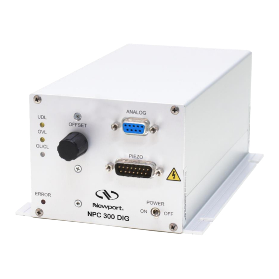
How to operate the digital amplifier series NPCxxxDIG 8.1 Common Introduction Our line of digital piezo amplifiers d-Drive from Newport Corporation has now been expanded with the addition of the OEM amplifier series NPCxxxDIG including NPC300DIG with 300mA output current. These amplifiers are designed for use as a single unit in industrial settings. It is compact, robust, and mountable in different manners and is highly reliable. -
Page 13: Back Panel
8.2.2 Back Panel... -
Page 14: Function
8.3 Function The following sketch shows the function groups of the amplifier: sketch 1: function groups of the amplifier www.newport.com... - Page 15 The command for the controller consists of the analog signal applied to the MOD input, the digital value given by the encoder “OFFSET” and the digital value from the RS232 interface. The slew rate of the amplifier can be adapted to your system using the "slew rate" limiter or the 4th order low pass filter, i.e.
- Page 16 Using the notch filter might increase noise. The PID-specific parameters kp, ki, and kd are stored in the actuator’s ID-chip by default. These parameters will work for most applications. Depending on your special application and load, the mechanical response can be optimized. www.newport.com...
-
Page 17: Technical Data
8.3.1 Technical Data NPC50DIG NPC300DIG 10 – 30 VDC Input voltage: Power supply connector: low voltage socket with 2.1mm-pin Input current: max. 2.5A @ 10V max. 5.5A @ 10V max. 1.0A @ 30V max. 2.5A @ 30V Power consumption: max. 30W max. -
Page 18: Mod/Mon
To generate an output of 0...+10V the control deviation is divided by 2 and +5 V is added. To calculate the control deviation back from the measured monitor voltage, take the following formula: Uerr = (Umon – 5V) * 2 Uerr = -10V...+10V Umon = 0...+10V If the controller is properly adjusted the value is +5 V. www.newport.com... -
Page 19: Pinning
4) absolute closed loop control deviation: |Uerr| = Ucom – Umes |Uerr| = 0...+10V 5) the actuator voltage -20V...+130V converts to 0...+10V; to calculate the actuator voltage back from the measured monitor voltage, take the following formula: Uactuator = (Umon * 15) – 20V 6) The position voltage in open loop (OL) is greater than in closed loop. -
Page 20: Communication & Commands
(please refer to the manual of your operating system). A serial connection cable (included) is required to connect to your computer. The properties of the COM port are: 115200 baud, 8 bit, no parity, 1 stop bit, software handshake (XON / XOFF). www.newport.com... -
Page 21: Commands
8.4.2 Commands global commands: <command> Enter command description dprpon switch on the cyclic output of the current actuator position value * dprpof switch off the cyclic output of the current actuator position value dprson switch on the automatic output of the status register when status of amplifier is changed dprsof switch off the automatic output of the status register when status... - Page 22 0.4 to 800 [sec/decade] scan type 0 = scan function off 1 = sine scan (one period) 2 = triangle scan (one period) 3 = sine scan (two periods) 4 = triangle scan (two periods) start scan without value: request scan state www.newport.com...
- Page 23 1 = starts scan trgss trigger generation stroke position start minimum: >0.2% of total stoke to maximum: total stroke minus 0.2% of total stroke [µm] or [mrad] trgse trigger generation stroke position end minimum: >0.2% of total stoke to maximum: total stroke minus 0.2% of total stroke [µm] or [mrad], always keep: trgse >...
-
Page 24: Status Register
0 to 100% √ √ √ √ √ offset 0 to 100% √ √ √ frequency 0.1 to 9999.9Hz √ sweep time 0.4 to 800sec/dec √ √ duty cycle 0.1 to 99.9% table 9: functions and their parameters www.newport.com... -
Page 25: Output Of Trigger Signals
sweep The amplitude that has been [Hz] selected is the peak to peak value. The sweep depth is fixed by 1Hz 10000 to 10kHz (4 decades). In the 1000 meantime, frequency increases logarithmically.This case represents "sweep" parameter increasing frequency per decade. 1Tsw 2Tsw 3Tsw... - Page 26 This function is parameterized by trgss, trgse, trgsi und trglen. On each period, only one trigger appears, the trigger point “moves” at every period by its increment (trgsi). After reaching the end position (trgse) the trigger point “moves” backward. www.newport.com...
- Page 27 … trgse – n * trgsi trgse (end point) trgse (end point) trigger at trgss + n * trgsi (n = 2) trigger at trgss + n * trgsi (n = 1) start point (trgss) The recognition of edges works as follows: During the rising edge, the highest measurement value (position) will be stored.
-
Page 28: Scan Function
The scan starts with “ss,1”. During a scan, the status can be requested with "ss<CR>". The answer “ss,2” means the scan is still running, “ss,0” indicates the scan is complete. A running scan can be aborted by setting the status to zero (ss,0<CR>). www.newport.com... - Page 29 Example: scan sine , 100% amplitude, 0% offset, frequency = 0,2Hz gfsin,0.2<CR> gasin,100<CR> gosin,0<CR> scan type: sct,1 start scan: ss,1 sketch 5: output voltage of a sine scan (open loop) Application: The combined use of trigger generation and scan function permits a highly exact scan of a probe. Acceleration forces (and with it oscillations) are minimized by using a sine function, and actions can be initiated by the trigger generation at exactly defined actuator positions.
-
Page 30: Handling
Please do not continue working after your actuator has been damaged. The values of calibration are valid only for a specified assembly configuration. Any change in the assembly configuration can cause the modes OVL or UDL. Please provide us with your assembly configuration in advance. www.newport.com... -
Page 31: Controller Adjustment
10 Controller Adjustment When any actuator made by Newport Corporation is connected to the NPCxxxDIG, amplifier their specific values are read from the actuator’s ID-chip. The Digital Signal Processor (DSP) of the amplifier is set with these values. These parameters were investigated in the Newport Corporation laboratory and ensure safe function of the actuator. -
Page 32: Troubleshooting
Aliasing: If the signal read out sequence is lower than half of the correspond to the applied working frequency only the serial data is affected. The real motion signal value values are not affected. table 11: errors www.newport.com... -
Page 33: Error Register
11.1 Error Register The error register is a 16bit register. Each bit describes different error. Once error has occurred the error register changes and error message as a decimal number will be issued via interface. „ “ CR LF. ?ERR,error The decimal sum of all bits results the error value: description decimal... -
Page 34: Your Notes
12 Your Notes www.newport.com...
Need help?
Do you have a question about the NPC DIG Series and is the answer not in the manual?
Questions and answers