Table of Contents
Advertisement
Quick Links
Advertisement
Table of Contents

Related Manuals for Newport NPC Series


Summary of Contents for Newport NPC Series
- Page 1 Instruction Manual Voltage Piezo Amplifier Series NPC and NPCSG Models: NPC3 & NPC3SG NPC120 & NPC120SG Read carefully before switching on the power! Please see also instructions for safety when using piezoelectric actuators and power supplies!
- Page 2 English version: last change 2017-02-16 by TP www.newport.com...
-
Page 3: Table Of Contents
Table of contents Introduction ........................4 Certification of Newport Corporation ................4 Declaration of Conformity ..................... 5 Purchased Part Package ....................6 Instructions for using piezo electrical elements and power supplies ......6 Safety Instructions ......................7 Installation, Power Supply ..................... 8 Operation ........................ -
Page 4: Introduction
1 Introduction This manual describes the piezo amplifiers NPC & NPCSG from Newport Corporation. You will also find additional information regarding piezoelectric products. Definition: All systems from Newport Corporation such as electronics, actuators and optical systems are called units. If you have any problems please contact the manufacturer of the system: Newport Corporation, 1791 Irvine Ave. -
Page 5: Declaration Of Conformity
2016 Type of Equipment: Electrical equipment for measurement, control and laboratory use in industrial locations. Manufacturer: Newport Corporation 1791 Deere Avenue Irvine, CA 92606 U.S.A. We hereby certify that the above described device in its conception, construction and form put by us into circulation is in accordance with all relevant essential requirements of the EMC Directive 2014/30/EU. -
Page 6: Purchased Part Package
5 Instructions for using piezo electrical elements and power supplies Piezoelectric actuators from Newport Corporation are controlled by voltages up to 150V. These values can be quite hazardously. Therefore read the installation instructions carefully and only authorized personal should handle the power supply. -
Page 7: Safety Instructions
For information about where the user can drop off the waste equipment for recycling, please contact your local Newport representative. Control of Hazardous Substances... -
Page 8: Installation, Power Supply
Please use only original parts from Newport Corporation. Newport Corporation does not give any warranty for damages or malfunction caused by additional parts not supplied by Newport Corporation. Additional cables or connectors will change the calibration and other specified data. This can change the specified properties of the units and cause them to malfunction. -
Page 9: Operation
Always grasp the plug portion when unplugging the power plug. Pulling on the power cord may expose or snap the core wire, or otherwise damage the power cord. If the cord is damaged, this could cause an electricity leak and result in a fire or electrical shock. CAUTION! ... -
Page 10: Maintenance And Inspection
Piezo amplifier for one PZT actuator; RS232/USB interface; for piezo actuating system without feedback sensor inside, 120mA current per actuator NPC120SG Piezo amplifier for one PZT actuator; RS232/USB interface; for piezo actuating system with feedback sensor inside (strain gauge), 120mA current per actuator www.newport.com... -
Page 11: Keywords
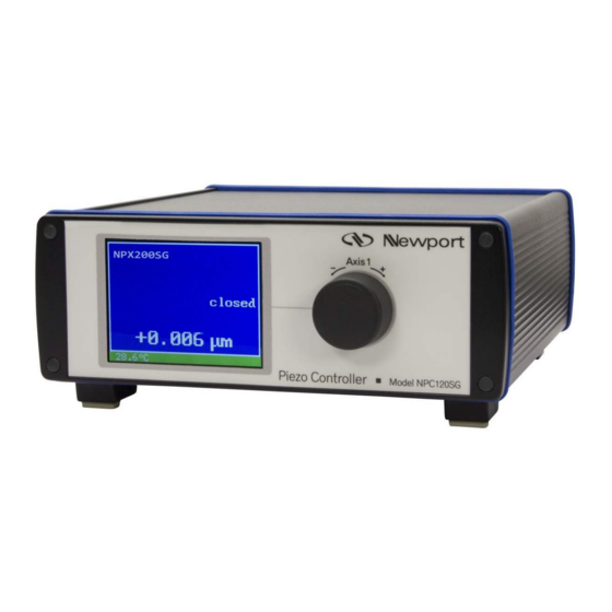
7.1 Keywords GRAPHIC DISPLAY Dimmable 3.5” TFT full colour graphic, 320x240 Pixel; constantly shows all values and status information ENCODER KNOB For manually voltage or position adjustment and for switching on/off the CLOSED LOOP mode (NPC3SG only) CLOSED LOOP Operating mode for piezo actuating systems with integrated feedback sensor system, position accuracy is constantly controlled OPEN LOOP Operating mode for actuating systems without feedback sensor inside;... -
Page 12: User Elements / Connections
The amplifiers come as a stand-alone device with standard PC interface RS232 and USB. A dimmable graphic display constantly shows all status information such as voltage and motion. www.newport.com... -
Page 13: Block Diagram
Each piezo can be controlled separately by turning the voltage offset, by applying an analog voltage signal of 0 to 10V or by PC interface. The voltage of the monitor output correspondents to either applied piezo voltage (NPC3, NPC120) or completed motion (NPC3SG, NPC120SG). -
Page 14: Amplifier Without Integrated Feedback Controller
Any system delivered as open loop mode cannot be modified to closed loop later on. Any closed loop system can be easily calibrated to a different closed loop piezo afterwards. This is only possible at Newport Corporation and will cause additional effort and costs. Please contact our sales team for more information. -
Page 15: Graphic Display Npc3, Npc3Sg
7.4.3 Graphic display NPC3, NPC3SG The graphic display shows the following status information: name of axis of actuator remote mode activated “REMOTE“ name of actuator (Please note this example is not in Remote) operating mode “closed loop” actuator position (only NPC3SG) (only NPC3SG) operation mode Piezo voltage... -
Page 16: Handling
The monitor output can be switch in different modes via RS232 or USB interface. (x describes the number of channel) monwpa,x,0: Output of a voltage proportional to the actuator voltage. This mode will set the monitor output signal fixed to its characteristics. Shown in diagram 1. diagram 1 www.newport.com... -
Page 17: Monitor Npc3, Npc120
Based on this a signal of 0V is related to an applied voltage of –20V and +10V is related to +130V. In closed loop the minimum and maximum values never reaches caused by the closed loop control reserve. monwpa,x,1: Output of a voltage proportional to the actuator position (delivery status). Shown in diagram 2. -
Page 18: Configuration Rs232
ERR? shows the last occurred error light display brightness chart 2: command list overview NPC3, NPC3SG: The numbers for the channels starts with „0“. Connector “PIEZO 1” equals channel number “0”. The format of the command is: <command>,<channel>,<value> www.newport.com... -
Page 19: Commands
NPC120, NPC120SG: Set command is without channel number. The format of the command is: <command>,<value> Please use dot “.” if commands included a value to separate decimal places. 8.3.3 Commands command 'setk' call: setk,<ch>,<0|1> example: setk,0,1 answer: none set the actuator on channel 0 (PIEZO 1) to remote control The command setk switches the remote control for one channel <ch>... - Page 20 During soft start the modulation input and the encoder are disabled. After soft start the amplifier is working normally. Command without value reads out the current value. command 'fenable' www.newport.com...
-
Page 21: Examples
call: fenable,<ch>,<0|1> example: fenable,0,1 answer: none the soft start function is switched on for the channel 0 (PIEZO 1) This command 'fenable' enables the soft start function for the given channel. After switching on the system the soft start function is started for 10 seconds to initiate the actuator. While this routine the actuator is moved once through the whole motion range and back. -
Page 22: Calibration Of Encoder
10000 If the absolute value of deltaValue is higher than enclim, deltaValue will set to enclim with the same prefix. The above-named commands are valid for all modes. www.newport.com... - Page 23 special commands for encoder: normal with acceleration (EM0) call: encexp,<1...10> example: encexp,3 answer: none the exponent is set to 3 adjustable interval with and without acceleration (EM1,2) call: encstol,<0.001…150.000> example:encstol,1.000 the step size for„open loop“ is set to 1V answer: none The numerical resolution of 1mV will be not achieved due to the resolution of the DAC of 16 bit.
-
Page 24: Technical Data
ASI function, over voltage protection, over temperature protection, short circuit proof, dimmable display main power supply 24VDC / 2,5A (wide range power supply 100-240VAC is included in the shipment) order info NPC3 NPC3SG NPC120 NPC120SG Chart 5: Technical Data NPC3 [SG], NPC120 [SG] www.newport.com... -
Page 25: Pin Assignment
(for NPC120SG please use channel 3) The MOD/MON adapter cable is part of the delivery. If the use of a self-made adapter cable necessary, no liability for the functionality and the system parameters can be guaranteed. Please contact Newport Corporation for detailed information. -
Page 26: Rs232 D-Sub 9Pin
8.5.5 Main Supply Voltage The NPC3, NPC3SG, NPC120 and NPC120SG needs 24VDC and require at least a current of 2.5A. The 2.1mm barrel connector has the following layout. A wide range power supply 100- 240VAC is included in the shipment. +24V Ground www.newport.com... -
Page 27: Troubleshooting
9 Troubleshooting During operation the display can show a defined error code. A reason can be the buffer overflowing, a temperature value out of range or a overshooting of the actuating system. Promptly the error code is provided on the display and on the connected PC too. The code is 16bit wide and it’s binary-coded (ERROR,FWch0,FWch1,FWch2). -
Page 28: Your Notes
Your Notes www.newport.com...