GORMAN-RUPP PUMPS 0 Series Installation, Operation, And Maintenance Manual With Parts List
Hide thumbs
Also See for 0 Series:
Table of Contents
Advertisement
Quick Links
BC
OM‐01141‐02
November 18, 2005
Rev. A 07‐05‐2013
INSTALLATION, OPERATION,
AND MAINTENANCE MANUAL
WITH PARTS LIST
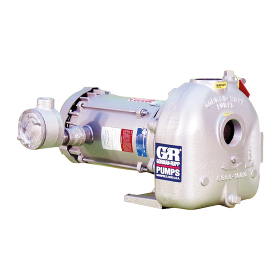
0 SERIES PUMP
MODEL
03C51-B
THE GORMAN‐RUPP COMPANY D MANSFIELD, OHIO
www.grpumps.com
D
GORMAN‐RUPP OF CANADA LIMITED
ST. THOMAS, ONTARIO, CANADA
Printed in U.S.A.
e
Copyright by the Gorman‐Rupp Company
Advertisement
Table of Contents

Related Manuals for GORMAN-RUPP PUMPS 0 Series


Summary of Contents for GORMAN-RUPP PUMPS 0 Series
- Page 1 OM‐01141‐02 November 18, 2005 Rev. A 07‐05‐2013 INSTALLATION, OPERATION, AND MAINTENANCE MANUAL WITH PARTS LIST 0 SERIES PUMP MODEL 03C51-B THE GORMAN‐RUPP COMPANY D MANSFIELD, OHIO www.grpumps.com GORMAN‐RUPP OF CANADA LIMITED ST. THOMAS, ONTARIO, CANADA Printed in U.S.A. Copyright by the Gorman‐Rupp Company...
- Page 2 Register your new Gorman‐Rupp pump online at www.grpumps.com/register. Valid serial number and e‐mail address required. RECORD YOUR PUMP MODEL AND SERIAL NUMBER Please record your pump model and serial number in the spaces provided below. Your Gorman‐Rupp distributor needs this information when you require parts or service. Pump Model: Serial Number:...
-
Page 3: Table Of Contents
TABLE OF CONTENTS INTRODUCTION ..........PAGE I - 1 SAFETY ‐... - Page 4 TABLE OF CONTENTS (continued) PUMP MAINTENANCE AND REPAIR ‐ SECTION E ....PAGE E - 1 STANDARD PERFORMANCE CURVE ........PAGE E - 1 PARTS LISTS: Pump End Assembly...
-
Page 5: Introduction
Gorman‐ Rupp pump. Immediate hazards which WILL result in This pump is an 0 Series, enclosed impeller, self‐ severe personal injury or death. These priming centrifugal model, designed with straight instructions describe the procedure re... -
Page 6: Safety - Section A
0 SERIES OM-01141 SAFETY ‐ SECTION A This information applies to 0 Series ba 6. Vent the pump slowly and cau sic pumps. Gorman‐Rupp has no con tiously. trol over or particular knowledge of the 7. Drain the pump. power source which will be used. Refer to the manual accompanying the power source before attempting to begin oper... - Page 7 OM-01141 0 SERIES low the pump to completely cool before servicing. Do not remove plates, covers, gauges, pipe plugs, or fittings from an over heated pump. Vapor pressure within the Pumps and related equipment must be in pump can cause parts being disen...
-
Page 8: Installation - Section B
0 SERIES OM-01141 INSTALLATION - SECTION B Review all SAFETY information in Section A. configuration, and priming must be tailored to the specific application. Since the pressure supplied Since pump installations are seldom identical, this to the pump is critical to performance and safety,... -
Page 9: Preinstallation Inspection
OM-01141 0 SERIES PREINSTALLATION INSPECTION good repair and with adequate capacity to prevent injuries to personnel or dam The pump assembly was inspected and tested be age to equipment. Suction and dis fore shipment from the factory. Before installation, charge hoses and piping must be re... -
Page 10: Line Configuration
0 SERIES OM-01141 Line Configuration Strainers If a strainer is furnished with the pump, be certain Keep suction and discharge lines as straight as to use it; any spherical solids which pass through a possible to minimize friction losses. Make mini... -
Page 11: Suction Line Positioning
OM-01141 0 SERIES Suction Line Positioning NOTE The pipe submergence required may be reduced The depth of submergence of the suction line is by installing a standard pipe increaser fitting at the critical to efficient pump operation. Figure 2 shows end of the suction line. -
Page 12: Alignment
0 SERIES OM-01141 enough to prevent clogging, but not so large as to between the driving and the driven shafts. Refer to affect pump discharge capacity. the coupling manufacturer's service literature. Align spider insert type couplings by using calipers to measure the dimensions on the circumference ALIGNMENT of the outer ends of the coupling hub every 90_. -
Page 13: Drive Belt Tensioning
OM-01141 0 SERIES the sides of the pulleys to ensure that the pulleys are properly aligned (see Figure 5). In drive sys tems using two or more belts, make certain that the belts are a matched set; unmatched sets will cause Do not operate the pump without the accelerated belt wear. -
Page 14: Operation - Section C
OM-01141 0 SERIES OPERATION - SECTION C Review all SAFETY information in Section A. coming liquid to evacuate the air. After the pump and piping system have completely filled, evacu Follow the instructions on all tags, labels and ate any remaining air pockets in the pump or suc... -
Page 15: Operation
OM-01141 0 SERIES Consult the operating manual furnished with the filled, adjust the throttling valve to the required flow power source before attempting to start the power rate. source. Leakage If an electric motor is used to drive the pump, re... -
Page 16: Pump Vacuum Check
OM-01141 0 SERIES maximum permissible operating pressure shown Cold Weather Preservation on the pump performance curve. (See Section E, In below freezing conditions, drain the pump to Page 1.) prevent damage from freezing. Also, clean out any solids by flushing with a hose. Operate the pump for approximately one minute;... -
Page 17: Troubleshooting - Section D
OM-01141 0 SERIES TROUBLESHOOTING - SECTION D Review all SAFETY information in Section A. Before attempting to open or service the pump: 1. Familiarize yourself with this man ual. 2. Lock out or disconnect the power source to ensure that the pump will remain inoperative. - Page 18 OM-01141 0 SERIES TROUBLE POSSIBLE CAUSE PROBABLE REMEDY Impeller or other wearing parts worn Replace worn or damaged parts. PUMP STOPS OR FAILS TO DELIVER or damaged. Check that impeller is properly RATED FLOW OR centered and rotates freely. PRESSURE (cont.) Impeller clogged.
-
Page 19: Preventive Maintenance
OM-01141 0 SERIES PREVENTIVE MAINTENANCE equipped) between regularly scheduled inspec tions can indicate problems that can be corrected Since pump applications are seldom identical, and before system damage or catastrophic failure oc pump wear is directly affected by such things as curs. - Page 20 0 SERIES OM-01141 PUMP MAINTENANCE AND REPAIR ‐ SECTION E MAINTENANCE AND REPAIR OF THE WEARING PARTS OF THE PUMP WILL MAINTAIN PEAK OPERATING PERFORMANCE. STANDARD PERFORMANCE FOR PUMP MODEL 03C51-B Based on 70_ F (21_ C) clear water at sea level Contact the Gorman‐Rupp Company to verify per...
- Page 21 OM-01141 0 SERIES PARTS PAGE SECTION DRAWING Figure 1. Pump Model 03C51-B PAGE E - 2 MAINTENANCE & REPAIR...
- Page 22 0 SERIES OM-01141 PARTS LIST Pump Model 03C51-B (From S/N 1341129 Up) If your pump serial number is followed by an “N”, your pump is NOT a standard production model. Contact the Gorman‐Rupp Company to verify part numbers. ITEM PART...
- Page 23 OM-01141 0 SERIES PUMP AND SEAL DISASSEMBLY 4. Check the temperature before opening any covers, plates, or AND REASSEMBLY plugs. 5. Close the suction and discharge Review all SAFETY information in Section A. valves. Follow the instructions on all tags, label and de...
- Page 24 0 SERIES OM-01141 the seal spring will be released as the impeller is re After removing the shaft and bearings, clean and moved. Retain the impeller key (7). inspect the bearings in place as follows. Remove the impeller adjusting shims (16). Tie and tag the shims or measure and record their thick...
- Page 25 OM-01141 0 SERIES If bearing replacement is required, use a suitable NOTE bearing puller to remove the bearings from the Position the bearings (18 and 20) on the shaft with shaft. the bearing shields facing away from each other. Heat the bearings to a uniform temperature no...
- Page 26 0 SERIES OM-01141 Lubricate the pedestal as indicated in LUBRICA Handle the seal parts with extreme care to prevent TION. damage. Be careful not to contaminate precision finished faces; even fingerprints on the faces can shorten seal life. If necessary, clean the faces with a Seal Reassembly and Installation non‐oil based solvent and a clean, lint‐free tissue.
- Page 27 OM-01141 0 SERIES Subassemble the rotating element into the retainer and bellows. Lubricate the I.D. of the bellows with water, and slide this subassembly over the shaft until the polished faces contact. This seal is not designed for operation at temperatures above 160_F (71_C).
- Page 28 0 SERIES OM-01141 Vane Plate and Pump Casing Installation LUBRICATION Seal Assembly Clean the mating surfaces between the vane plate and seal plate to remove all of the old adhesive The seal assembly is lubricated by the medium be sealant. Apply a thin film of “3M Adhesive No. 847”...
- Page 29 For U.S. and International Warranty Information, Please Visit www.grpumps.com/warranty or call: U.S.: 419-755-1280 International: +1-419-755-1352 For Canadian Warranty Information, Please Visit www.grcanada.com/warranty or call: 519-631-2870 THE GORMAN‐RUPP COMPANY D MANSFIELD, OHIO GORMAN‐RUPP OF CANADA LIMITED ST. THOMAS, ONTARIO, CANADA...
Need help?
Do you have a question about the 0 Series and is the answer not in the manual?
Questions and answers