Table of Contents
Advertisement
Quick Links
This manual covers the following models:
• T605-2
Thermostat Applications Guide
D
e
s
c
i r
t p
o i
n
Gas or Oil Heat
Electric Furnace
Heat Pump (No Aux. or Emergency Heat)
Heat Pump (with Aux. or Emergency Heat)
Multi-stage Systems
Heat Only Systems
Heat Only Systems - Floor or Wall Furnaces
Cool Only Systems
Millivolt
Table of Contents
Una versión española de este
manual puede ser descargada
en www.pro1iaq.com
® U.S. Registered Trademark. Patents pending.
Copyright © 2010 Pro1 IAQ, Inc. All rights reserved.
INSTALLATION MANUAL
Power Type
Battery Power
Hardwire (Common Wire)
Yes
Hardwire (Common Wire) with Battery Backup
Yes
Yes
No
No
Yes
Yes
Yes
Yes
Page
A trained, experienced technician
must install this product.
2
3
Carefully read these instructions. You
4
could damage this product or cause a
5
hazardous condition if you fail to follow
6
these instructions.
7
8
9
10
Need Help?
11
12
For assistance with this product please
visit http://www.pro1iaq.com or call Pro1
Customer Care toll-free at 888-Pro1iaq
(776-1427) during normal business hours
(Mon-Fri 9 AM - 6 PM Eastern)
1
Rev. 1043
Advertisement
Table of Contents

Related Manuals for Pro1 IAQ TRUE COMFORT III T605-2


Summary of Contents for Pro1 IAQ TRUE COMFORT III T605-2
-
Page 1: Table Of Contents
Una versión española de este (776-1427) during normal business hours manual puede ser descargada (Mon-Fri 9 AM - 6 PM Eastern) en www.pro1iaq.com ® U.S. Registered Trademark. Patents pending. Copyright © 2010 Pro1 IAQ, Inc. All rights reserved. Rev. 1043... -
Page 2: Installation Tips
INSTALLATION TIPS Wall locations The thermostat should be installed approximately 4 to 5 feet above the floor. Select an area with average temperature and good air circulation. Do not install thermostat in locations: • Close to hot or cold air ducts •... -
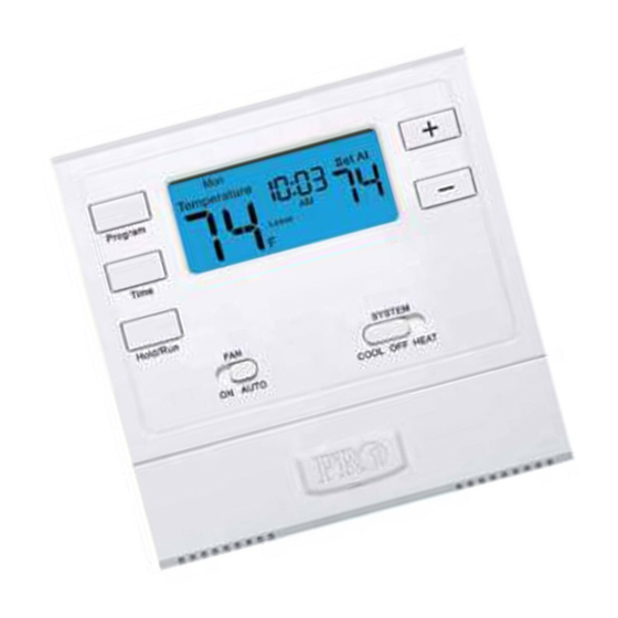
Page 3: Thermostat Quick Reference
Getting to know your thermostat System operation indicators: ON will NOTE: The compressor delay Days of the display when the feature is active if week and time COOL or HEAT is on. flashing. The compressor will not turn on until the 5 minute delay has elapsed. -
Page 4: Subbase Installation
SUBBASE INSTALLATION Caution: Mercury Notice: All of Pro1’s products are Electrical Hazard mercury free. However, if the Failure to disconnect the product you are replacing power before beginning to contains mercury, dispose of it install this product can cause properly. Your local waste electrical shock or equipment management authority can give damage. -
Page 5: Wiring
WIRING Caution: Electrical Hazard Warning: Failure to disconnect the power All components of the control before beginning to install this system and the thermostat product can cause electrical installation must conform to shock or equipment damage. Class II circuits per the NEC Code. Wiring If you are replacing a thermostat, make note of the terminal connections on the... -
Page 6: Wiring Diagrams
WIRING DIAGRAMS Power supply Factory-installed jumper. Remove only when installing on 2-transformer systems. Use either O or B terminals for changeover valve. Use a small piece of wire (not supplied) to connect W and Y terminals. Set fan operation switch to electric. Optional 24 VAC common connection when thermostat is used in battery power mode. -
Page 7: Technician Setup
TECHNICIAN SETUP MENU Gas or Electric Setup Gas: For systems that control the fan during a call for heat, put the fan operation switch to the GAS position. Electric: The thermostat operation switch should be put in the ELEC position. This setting allows the thermostat to operate the fan when the fan relay is connected to the G terminal. -
Page 8: Technician Setup Menu
TECHNICIAN SETUP MENU Technician Setup Menu This thermostat has a technician setup menu Configure the installer options as desired using the table below. for easy installer configuration. To setup the thermostat for your particular application: Use the keys to Move the SYSTEM switch to OFF. change settings and the Program key to move from one option to the next. -
Page 9: Mounting And Battery Installation
MOUNT THERMOSTAT & BATTERY INSTALLATION Mount Thermostat Align the 4 tabs on the subbase with corresponding slots on the back of the thermostat, then push gently until the thermostat snaps in place. -
Page 10: Programming The Thermostat
PROGRAMMING THE THERMOSTAT Set Time Follow the steps below to set the day of the week and current time: Press TIME Day of the week will be flashing. Use the key to select the current day of the week. Press TIME The current hour is flashing. -
Page 11: Programming The Thermostat (Cont)
PROGRAMMING THE THERMOSTAT You can use the table below to plan your customized program schedule. Programming Table Setpoint Setpoint Day of the Events Time Temperature Temperature Week (Heat) (Cool) Weekday Wake Leave Return Sleep Saturday Wake Leave Return Sleep Sunday Wake Leave Return... -
Page 12: Specifications
32º to +105º (0º to +41ºC) Operating humidity 90% non-condensing maximum Dimensions of thermostat 4.7”W x 4.4”H x 1.1”D Pro1 IAQ Inc. 1111 S. Glenstone Suite 2-100 Spring eld, MO 65804 Toll-free: 1-888-Pro1iaq (776-1427) Toll Number (Outside the USA): 330-821-3600 Web: http://www.pro1iaq.com...
Need help?
Do you have a question about the TRUE COMFORT III T605-2 and is the answer not in the manual?
Questions and answers