Advertisement
Quick Links
Installation Manual
Pro1 Technologies
P.O. Box 3377
Springfield, MO 65808-3377
Toll Free : 888-776-1427
Web: www.pro1iaq.com
Hours of Operation: M-F 9AM - 6PM Eastern
Thermostat Application Guide
Description
Gas or Oil Heat
Electric Furnace
Heat Pump (No Aux. or Emergency Heat)
Heat Pump (With Electric Aux.)
Heat Pump (With Gas Aux.)
Multi-Stage Systems
Heat Only Systems - Floor or Wall Furnace
Cool Only Systems
High, Medium and Low Fan Speed
Millivolt
Emergency Heat
Conventional Single Stage Furnace
Geothermal
Table of Contents
Installation Tips
Thermostat Quick Reference
Base Module Mounting Tips
Wiring
Technician Setup
Establishing Communication
Network Specifications
Specifications
U.S. Registered Trademark. Patents pending
1
Copyright
2020 All Rights Reserved.
Installation Tips
Mount Thermostat
Align the 4 tabs on the subbase
with corresponding slots on the
back of the thermostat, then push
gently until the thermostat snaps
in place.
Battery Installation
R
Important:
High quality alkaline batteries are recommended.
Rechargeable batteries or low quality batteries
do not guarantee a 1-year life span.
Insert 2 AA
Alkaline batteries
(included). High
quality alkaline
batteries are
recommended.
Located on the back of thermostat.
3
T731W(O)
Power Type
Battery Power
Hardwire (Common Wire)
Yes
Hardwire (Common Wire) with
Yes
Battery Backup
Yes
Yes
A trained, experienced
No
Yes
technician must install this
Yes
product.
Yes
Carefully read these
Yes
instructions. You could damage
No
this product or cause a
No
Yes
hazardous condition if you fail
Yes
to follow these instructions.
Page
Una version en español de este
2-3
manual se puede descargar en
4-5
la pagina web de la compañia.
6-7
8-11
12-16
17-18
19
20
Battery installation is
optional if thermostat is
hardwired (R and C terminal
connected to 24V power).
Wall Locations
The thermostat should be installed approximately 4 to 5 feet above the
floor. Select an area with average temperature and good air circulation.
Installation Tip
Pick an installation location that is easy for
the user to access. The temperature of the
location should be representative of the
building.
Subbase Installation
Horizontal Mount
Vertical Mount
For vertical mount put one screw on the top
and one screw on the bottom.
For horizontal mount put one screw on the
left and one screw on the right.
Rev. 2010
Getting to know your thermostat
thermostat in locations:
• Close to hot or cold air ducts
• That are in direct sunlight
• With an outside wall behind
the thermostat
• In areas that do not require
conditioning
• Where there are dead spots
or drafts
(in corners or behind doors)
• Where there might be
concealed chimneys or
pipes
Installation Tip:
Electrical Hazard
Failure to disconnect the power before
beginning to install this product can
cause electrical shock or equipment
damage.
Mercury Notice
All of our products are mercury free.
However, if the product you are
replacing contains mercury, dispose of
it properly. Your local waste
management authority can give you
instructions on recycling and proper
disposal.
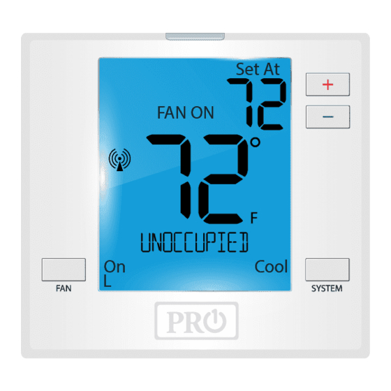
Thermostat Quick Reference
LCD
Glow in the Dark Light Button
Setpoint Buttons
Fan Button
System Button
Occupancy Sensor
(Occupancy Model Only)
Installation Tips
Do not install
2
4
Advertisement

Subscribe to Our Youtube Channel
Related Manuals for Pro1 IAQ T731W


Summary of Contents for Pro1 IAQ T731W
- Page 1 Installation Manual Installation Tips T731W(O) Wall Locations The thermostat should be installed approximately 4 to 5 feet above the floor. Select an area with average temperature and good air circulation. Pro1 Technologies Do not install P.O. Box 3377 thermostat in locations: Springfield, MO 65808-3377 •...
- Page 2 Base Module Mounting Tips Thermostat Quick Reference Base Module - PTAC Installation Set At Set At COOL ON COOL ON Range between the thermostat and the base module is up to 100 feet HEAT ON HEAT ON with no obstructions and up to 50 feet through standard building FAN ON FAN ON materials.
-
Page 3: Technician Setup
Wiring Wiring Caution: Warning: Wiring Note: Note: Electrical Hazard Failure to disconnect the power All components of the control The thermostat and Base Module The base module is before beginning to install this system and the thermostat come factory linked (communicating) packaged with labeled product can cause electrical installation must conform to... - Page 4 Technician Setup Technician Setup LCD Will Show Adjustment Options Default LCD Will Show Adjustment Options Default Tech Setup Steps Tech Setup Steps Select Gas (GS) for applications EL = Electric for thermostat This feature allows the installer O = Energized in cooling Change where the air handlers controls control...
-
Page 5: Establishing A Connection
The control range of temperature..44˚F to 90˚F (7˚C to 32˚C) Load rating..........1 amp per terminal, 1.5 amp To ensure paring success, place the T731W/O within a few feet of • maximum all terminals combined the Base module while pairing.
Need help?
Do you have a question about the T731W and is the answer not in the manual?
Questions and answers