
Related Manuals for C-Aire S110


Summary of Contents for C-Aire S110
- Page 1 MODELS S110 S280 S281 Fire Protection Air Compressor Owner’s Manual REV. A Sep/10/21...
-
Page 3: Table Of Contents
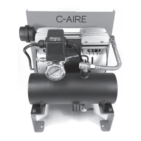
ELECTRICAL (continued �������������������������������������������������������������������������������������������������������������������������������������������������������������������������������������6 START UP ������������������������������������������������������������������������������������������������������������������������������������������������������������������������������������������������������������7 DIGITAL AMD OPERATING INSTRUCTIONS FOR 110 & 281 MODELS ������������������������������������������������������������������������������������������������������������������7 SYSTEM INSTALLATION DIAGRAMS ���������������������������������������������������������������������������������������������������������������������������������������������������������������������9 MAINTENANCE ��������������������������������������������������������������������������������������������������������������������������������������������������������������������������������������������������10 VALVES AND SWITCHES ������������������������������������������������������������������������������������������������������������������������������������������������������������������������������������10 S110 PARTS DIAGRAM ��������������������������������������������������������������������������������������������������������������������������������������������������������������������������������������11 S280 PARTS DIAGRAM ��������������������������������������������������������������������������������������������������������������������������������������������������������������������������������������12 S281 PARTS DIAGRAM ��������������������������������������������������������������������������������������������������������������������������������������������������������������������������������������13 TROUBLESHOOTING �����������������������������������������������������������������������������������������������������������������������������������������������������������������������������������������14 WARRANTY �������������������������������������������������������������������������������������������������������������������������������������������������������������������������������������������������������15... - Page 4 PARTS IDENTIFICATION 1. AIR FILTER 7. OUTLET 2. PRESSURE 8. MANUAL DRAIN VALVE SWITCH 3. SAFETY VALVE 9. MANIFOLD 4. PRESSURE GAUGE 10. DIGITAL AMD 11. SOLENOID 5. CHECK VALVE 6. TANK...
- Page 5 Misuse of this valuable and helpful air-power source may shorten its expected life as well as void the warranty of the entire unit� We ask you take the time to read this manual to ensure the dependable service you can expect from your C-Aire compressor�...
-
Page 6: Safety
SAFETY INSTALLATION DEFINITIONS SELECTING A LOCATION: C-Aire compressors are to be installed and operated in a clean, DANGER: Indicates a hazardous situation that, if not dry, well-lighted, and well-ventilated area� avoided, will result in death or serious injury� Provide at least 200 cubic feet of fresh air per 1 hp�... -
Page 7: Mounting The Compressor
MOUNTING THE COMPRESSOR CAUTION: Remove the compressor from the shipping packaging before mounting� MOUNTING OPTIONS FLOOR MOUNTING Riser Mark hole locations Install Mounting Bracket Place unit in chosen location, Riser: Mounts to 2 ½” riser or larger. mark 3 holes and remove unit. Drywall Clamps for 2 ½... -
Page 8: Inlet And Discharge Piping
fittings that are safe for the discharge pressure and temperature� WARNING: The compressor must be grounded� Ground- ing reduces the risk of electric shock� Certain C-Aire Models are equipped with a cord that has a grounding wire with a grounding plug� The plug must be plugged into an outlet that is installed and grounded in accor- dance with all local codes and ordinances�... -
Page 9: Electrical
LINE LINE Digital AMD MOTOR MOTOR BLACK Digital AMD DIGITAL Power Cord DIGITAL AMD SOLENOID SOLENOID BLACK PUMP S280 PRESSURE SWITCH S110 DIGITAL AMD WIRING DIAGRAM BLACK PLUG/BLANK SOLENOID BLACK WHITE MOTOR LT. GREEN GREEN WHITE POWER BLACK BLACK WHITE... -
Page 10: Start
START UP NOTE: There is no need to “break-in” your compressor� It has been tested and run at the factory by qualified personnel� When operating the compressor for the first time, do the following: 1� Perform an inspection of the compressor to ensure there are no obstructions that might interfere with moving parts� 2�... - Page 11 DIGITAL AMD OPERATING INSTRUCTIONS (CONTINUED) To unlock, repeat the previous process until the SETTINGS Pressing the mode button a fourth time, the 7DAYS LOCKED light turns off� indicator will display the total number of starts in the last 7 days STARTS (The counter will not measure time if the unit has no power)�...
-
Page 12: System Installation Diagrams
Digital AMD eliminates the need for air pressure maintenance device. No AMD Permitted Adjustable: 5-55 PSI Air Source System pressure varies depending on size of system (S281) (S110) Air Source Dry Pipe Valve Braided Flex Hose Outlet (Available Accessory) Water in system... -
Page 13: Maintenance
■ Change air-intake filter(s)� The filter is located on the by C-Aire and do not require adjustment� However, if you want to top of the compressor (see parts identification item 1)� make adjustments to the Digital AMD, those instructions are on Twist the top cap off of the filter housing to access the... -
Page 14: S110 Parts Diagram
S110 PARTS DIAGRAM Mounting Bracket RM BRACKET Electrical Cord EL CORD115V-RM Capacitor EL CBB60 Capacitor Cover EL CBB60-C Soldenoid Valve EL SV3V1-06 Check Valve BR 37525 Safety Relief Valve BR SV-25-70 Manifold BP 3M Digital Air Maintenance EL D0911 Device... -
Page 15: S280 Parts Diagram
S280 PARTS DIAGRAM Mounting Bracket RM BRACKET Flter Assembly FA S28 Capacitor EL CBB60 Capacitor Cover EL CBB60-C Drain Valve BR S28 Check Valve BR 37525 Discharge Tube DT S280 Pressure Gauge GA S280 Flex Hose DT 0504 10 Pressure Switch EL S280 11 Safety Relief Valve BR SV-25-125 12 Electrical Cord... -
Page 16: S281 Parts Diagram
S281 PARTS DIAGRAM Mounting Bracket RM BRACKET Solenoid Valve EL SV3V1-06 Check Valve BR 37525 Flex Hose DT 0504 Digital AMD EL D0911 Manifold BP 3M Power Cord EL CORD115V-RM Safety Relief Valve BR SV-25-70 Capacitor Cover EL CBB60-C 10 Capacitor EL CBB60 11 Filter Assembly FA S28... -
Page 17: Troubleshooting
• Tighten connections • Overheating Compressor • See “Overheating Compressor” • Knocking noise or internal pump issue • Internal pump issue • Call C-Aire for assistance • Clean check valve • Not unloading head pressure • Check Solenoid operation • Pump/motor hums •... -
Page 18: Warranty
WARRANTY OIL FREE COMPRESSOR C-Aire Inc� warrants its compressors to be free from defects in material and workmanship subject to the following provisions: STANDARD WARRANTY DURATION: 12 months from date of install� WHAT THE WARRANTY COVERS DURING THE WARRANTY DURATION: All components on the compressor except for those items listed in the section titled “What is excluded from warranty coverage”�... - Page 21 380 West 1st Street, Dresser, WI 54009 800�762�2247 - 651�462�3440 www�cairecompressors�com...
Need help?
Do you have a question about the S110 and is the answer not in the manual?
Questions and answers