Table of Contents
Advertisement
Quick Links
Advertisement
Table of Contents

Related Manuals for C-Aire S244


Summary of Contents for C-Aire S244
- Page 1 MODELS S244 S600 Fire Protection Air Compressor REV. A Dec/15/20 LL BP MANUAL...
-
Page 3: Table Of Contents
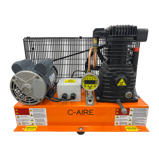
S600 PARTS DIAGRAM ��������������������������������������������������������������������������������������������������������������������������������������������������������������������������������������10 TROUBLESHOOTING �����������������������������������������������������������������������������������������������������������������������������������������������������������������������������������������11 WARRANTY �������������������������������������������������������������������������������������������������������������������������������������������������������������������������������������������������������12 Parts Identification 1. ELECTRICAL BOX 2. AIR FILTER 3. PUMP 4. DISCHARGE TUBE (S600)/HOSE (S244) 5. DIGITAL AMD (LOCATED BEHIND DIGITAL AMD) 6. MOTOR 8. SOLENOID 7. MANIFOLD 9. CHECK VALVE 10. SAFETY RELIEF VALVE... - Page 4 Misuse of this valuable and helpful air-power source may shorten its expected life as well as void the warranty of the entire unit� We ask you take the time to read this manual to ensure the dependable service you can expect from your C-Aire compressor�...
-
Page 5: Safety
INSTALLATION SELECTING A LOCATION: C-Aire compressors are to be installed and operated in a clean, dry, well-lighted, and well-ventilated area� Provide at least 200 cubic feet of fresh air per 1 hp� Ideal operating temperatures are between 32°F and 100°F�... - Page 6 MOUNTING THE COMPRESSOR CAUTION: Remove the compressor from the shipping packaging before mounting� FLOOR MOUNTING Mark hole loca�ons Place unit in chosen loca�on, mark 2 holes and remove unit. Floor Mount kits are included and include 2 anchor bolts, nuts, washers, and vibration absorption washers.
-
Page 7: Electrical
WARNING: The compressor must be grounded� Grounding reduces the risk of electric shock� Certain C-Aire Models are equipped with a cord that has a grounding wire with a grounding plug� The plug must be plugged into an outlet that is installed and grounded in accordance with all local codes and ordinances�... -
Page 8: Start
START UP NOTE: There is no need to “break-in” your compressor� It has been tested and run at the factory by qualified personnel� When operating the compressor for the first time, do the following: 1� Perform an inspection of the compressor to ensure there are no obstructions that might interfere with moving parts� 2�... - Page 9 To unlock, repeat the previous process until the SETTINGS mode button a fourth time, the 7DAYS Pressing the LOCKED light turns off� indicator will display the total number of starts in the last 7 days STARTS (The counter will not measure time if the unit has no power)� 24HRS 7 DAYS STARTS...
-
Page 10: System Installation Diagrams
SYSTEM INSTALLATION DIAGRAMS NOTE: Baseplate units are factory set to 10-20PSI� No AMD Permitted: Digital AMD eliminates the need for air pressure maintenance device. -
Page 11: Maintenance
A Digital AMD is used to detect the demand for compressed air and allow the motor to start� When the demand is satisfied, the motor stops� the Digital AMD is preset at the factory by C-Aire and does not require adjustment� However, if you want to make adjustments to the Digital AMD, those instructions are on page 5�... -
Page 12: S244 Parts Diagram
S244 PARTS DIAGRAM 1 Base Plate BP 03 2 Motor MR C168A 3 Belt Guard BG 03 4 Belt BT A-51 5 Solenoid EL SV3V1-06 6 Safety Relief Valve BR SV-25-70 7 Digital AMD EL D0911 8 Pump PM F 65A... -
Page 13: S600 Parts Diagram
S600 PARTS DIAGRAM 1 Base Plate BP 03 2 Motor MR C182A 3 Belt Guard BG 03 4 Belt BT A-59 5 Solenoid EL SV3V1-06 6 Discharge Tube DT 5050-REF 7 Digital AMD EL D0911 8 Pump PM F25A 9 Check Valve BR VCV33U 10 Manifold BP 3M... -
Page 14: Troubleshooting
• Pressure switch not making contact (S###) • See pressure switch adjustment • Knocking noise or internal pump issue • Internal pump problem • Call C-Aire for assistance • Check all fittings • WARNING: Bleed tank� Disassemble Check • Tank does not hold pressure when •... -
Page 15: Warranty
WARRANTY OIL FREE COMPRESSOR C-Aire Inc� warrants its compressors to be free from defects in material and workmanship subject to the following provisions: STANDARD WARRANTY DURATION: 12 months from date of install� WHAT THE WARRANTY COVERS DURING THE WARRANTY DURATION: All components on the compressor except for those items listed in the section titled “What is excluded from warranty coverage”�... - Page 17 380 West 1st Street, Dresser, WI 54009 800�762�2247 - 651�462�3440 www�cairecompressors�com...
Need help?
Do you have a question about the S244 and is the answer not in the manual?
Questions and answers
What is the maximum psi that can be reached with this compressor?
The maximum PSI for the C-Aire S244 compressor is 55 PSI.
This answer is automatically generated