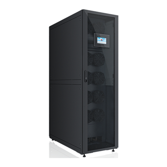
Huawei NetCol5000-A050 User Manual
In-row air cooled smart cooling product
Hide thumbs
Also See for NetCol5000-A050:
- User manual (311 pages) ,
- Quick manual (31 pages) ,
- User manual (232 pages)

Related Manuals for Huawei NetCol5000-A050


Summary of Contents for Huawei NetCol5000-A050
- Page 1 NetCol5000-A050 In-row Air Cooled Smart Cooling Product User Manual Issue Date 2021-09-17 HUAWEI TECHNOLOGIES CO., LTD.
- Page 2 Notice The purchased products, services and features are stipulated by the contract made between Huawei and the customer. All or part of the products, services and features described in this document may not be within the purchase scope or the usage scope. Unless otherwise specified in the contract, all statements, information, and recommendations in this document are provided "AS IS"...
-
Page 3: About This Document
NetCol5000-A050 In-row Air Cooled Smart Cooling Product User Manual About This Document About This Document Purpose This document describes the NetCol5000-A air cooled in-row precision smart cooling product in terms of its product overview, installation, power-on commissioning, operation and maintenance (O&M), and FAQ. It helps readers understand how to use and maintain the NetCol5000-A. - Page 4 NetCol5000-A050 In-row Air Cooled Smart Cooling Product User Manual About This Document Symbol Description Indicates a potentially hazardous situation which, if not avoided, could result in equipment damage, data loss, performance deterioration, or unanticipated results. NOTICE is used to address practices not related to personal injury.
- Page 5 NetCol5000-A050 In-row Air Cooled Smart Cooling Product User Manual About This Document Issue 03 (2020-02-20) Updated the description about the electric control box of the outdoor unit. Issue 02 (2020-01-06) Updated the safety information. Issue 01 (2019-06-30) This issue is the first official release.
-
Page 6: Table Of Contents
NetCol5000-A050 In-row Air Cooled Smart Cooling Product User Manual Contents Contents About This Document........................ ii 1 Safety Information........................1 1.1 General Safety..................................1 1.2 Personnel Requirements............................... 4 1.3 Electrical Safety..................................4 1.4 Installation Environment Requirements.......................... 6 1.5 Mechanical Safety................................... 8 1.6 Cooling System Safety.................................10... - Page 7 NetCol5000-A050 In-row Air Cooled Smart Cooling Product User Manual Contents 4.2.2.5 Drainpipe................................... 56 4.2.2.6 Pipe Support..................................57 4.2.2.7 Cables....................................57 4.3 Unpacking and Acceptance............................... 59 4.4 Installing the Indoor Unit..............................59 4.4.1 Checking the Nitrogen Pressure........................... 59 4.4.2 Removing the Pallet................................. 60 4.4.3 Removing the Transport Fasteners from the Compressor...................
- Page 8 NetCol5000-A050 In-row Air Cooled Smart Cooling Product User Manual Contents 4.9.4 Installing the Outdoor Unit Power Cable....................... 105 4.9.5 (Optional) Installing the Low-temperature Component Power Cable............106 4.9.6 Installing the Outdoor Unit Signal Cable....................... 107 4.9.7 Installing Cables for T/H Sensors Outside the Cabinet..................108 4.9.8 (Optional) Installing Teamwork and Monitoring Communications Cables..........111...
- Page 9 NetCol5000-A050 In-row Air Cooled Smart Cooling Product User Manual Contents 8.1.1 Data Record..................................173 8.1.2 Monthly Maintenance..............................174 8.1.3 Quarterly Maintenance..............................176 8.1.4 Yearly Maintenance................................ 177 8.2 Outdoor Unit Routine Maintenance..........................178 8.2.1 Monthly Maintenance..............................178 8.2.2 Semi-Annual Maintenance............................179 8.3 Water Cooling Module Routine Maintenance......................
- Page 10 NetCol5000-A050 In-row Air Cooled Smart Cooling Product User Manual Contents 12.10 How Do I Mute the Buzzer?............................301 12.11 How Can I Handle Active Alarms?.......................... 302 12.12 Deleting Historical Alarms............................303 12.13 How Do I Clear Component Runtime?........................304 12.14 How to Calibrate a Sensor............................304 12.15 How Do I Change the Password?..........................305...
-
Page 11: Safety Information
The "NOTICE", "CAUTION", "WARNING", and "DANGER" statements in this document do not cover all the safety instructions. They are only supplements to the safety instructions. Huawei will not be liable for any consequence caused by the violation of general safety requirements or design, production, and usage safety standards. - Page 12 NetCol5000-A050 In-row Air Cooled Smart Cooling Product User Manual 1 Safety Information General Requirements ● Do not install, use, or operate outdoor equipment and cables (including but not limited to moving equipment, operating equipment and cables, inserting connectors to or removing connectors from signal ports connected to outdoor facilities, working at heights, and performing outdoor installation) in harsh weather conditions such as lightning, rain, snow, and level 6 or stronger wind.
- Page 13 NetCol5000-A050 In-row Air Cooled Smart Cooling Product User Manual 1 Safety Information ● All cable holes should be sealed. Seal the used cable holes with firestop putty. Seal the unused cable holes with the caps delivered with the cabinet. The following figure shows the criteria for correct sealing with firestop putty.
-
Page 14: Personnel Requirements
Do not power on the equipment before it is installed or confirmed by professionals. 1.2 Personnel Requirements ● Personnel who plan to install or maintain Huawei equipment must receive thorough training, understand all necessary safety precautions, and be able to correctly perform all operations. ●... - Page 15 NetCol5000-A050 In-row Air Cooled Smart Cooling Product User Manual 1 Safety Information General Requirements Use dedicated insulated tools when performing high-voltage operations. AC and DC Power D ANGER Do not connect or disconnect power cables with power on. Transient contact between the core of the power cable and the conductor will generate electric arcs or sparks, which may cause fire or personal injury.
-
Page 16: Installation Environment Requirements
NetCol5000-A050 In-row Air Cooled Smart Cooling Product User Manual 1 Safety Information ● Do not perform any improper operations, for example, dropping cables directly from a vehicle. ● When selecting, connecting, and routing cables, follow local safety regulations and rules. - Page 17 NetCol5000-A050 In-row Air Cooled Smart Cooling Product User Manual 1 Safety Information vents, or feeder windows of the equipment room. Ensure that no liquid enters the equipment to prevent faults or short circuits. ● If any liquid is detected inside the equipment, immediately disconnect the power supply and contact the administrator.
-
Page 18: Mechanical Safety
NetCol5000-A050 In-row Air Cooled Smart Cooling Product User Manual 1 Safety Information 1.5 Mechanical Safety Hoisting ● Do not walk under hoisted objects. ● Only trained and qualified personnel should perform hoisting operations. ● Check that hoisting tools are available and in good condition. - Page 19 NetCol5000-A050 In-row Air Cooled Smart Cooling Product User Manual 1 Safety Information ● When climbing a ladder, take the following precautions to reduce risks and ensure safety: – Keep your body steady. – Do not climb higher than the fourth rung of the ladder from the top.
-
Page 20: Cooling System Safety
NetCol5000-A050 In-row Air Cooled Smart Cooling Product User Manual 1 Safety Information ● When moving the equipment by hand, wear protective gloves to prevent injuries. ● Move or lift the equipment by holding its handles or lower edges. Do not hold... -
Page 21: Others
NetCol5000-A050 In-row Air Cooled Smart Cooling Product User Manual 1 Safety Information Refrigerant Frostbite Refrigerant leakage may cause frostbite. Take protective measures (for example, wear antifreeze gloves) when handling refrigerant. Storage and Recycling ● Do not store devices near a heat source or under direct sunshine. -
Page 22: Product Description
NetCol5000-A050 In-row Air Cooled Smart Cooling Product User Manual 2 Product Description Product Description 2.1 Model Number Description Indoor Unit Model Number Description This document involves the following product models: ● NetCol5000-A050H40D2 ● NetCol5000-A050H4WD2 ● NetCol5000-A050H4WE2 ● NetCol5000-A050H40E2 ● NetCol5000-A050HRWE2 ●... - Page 23 NetCol5000-A050 In-row Air Cooled Smart Cooling Product User Manual 2 Product Description Meaning Description Model code 050: model code 050 Air supply mode H: horizontal flow Power supply 4: 380–415 V, 3 PH, 50/60 Hz R: 440–480 V, 3 PH, 60 Hz...
-
Page 24: Components
NetCol5000-A050 In-row Air Cooled Smart Cooling Product User Manual 2 Product Description Meaning Description Model code 055: model code 055 060: model code 060 080: model code 080 120: model code 120 Power supply 6: 220–240 V, 1 PH, 50/60 Hz M: 380–415 V, 3 PH, 50 Hz... -
Page 25: Indoor Unit
NetCol5000-A050 In-row Air Cooled Smart Cooling Product User Manual 2 Product Description 2.2.1 Indoor Unit Appearance Figure 2-3 Dimensions (unit: mm) (1) Cabinet connecting (2) Controller panel (3) Door lock (4) Front door (5) Mounting hole (6) Side panel (7) Rear door... - Page 26 NetCol5000-A050 In-row Air Cooled Smart Cooling Product User Manual 2 Product Description Figure 2-4 Holes in the smart cooling product (1) Power cable hole (Φ28 mm) on the top (2) Humidifier water inlet pipe hole (Φ43 mm) on the top (3) Signal cable hole (Φ28 mm) on the...
- Page 27 NetCol5000-A050 In-row Air Cooled Smart Cooling Product User Manual 2 Product Description Figure 2-5 Components (1) Fan (2) Condensate pump (3) Drainage check valve (4) Electric heater (5) Electrical box (6) Evaporator (7) Wet film humidifier (8) Compressor (9) Filter dryer...
- Page 28 NetCol5000-A050 In-row Air Cooled Smart Cooling Product User Manual 2 Product Description – The evaporator adopts the inner threaded copper pipe and blue hydrophilic aluminum foil to prevent water blowing due to condensate water accumulation and improve heat exchange performance. The V-type evaporator optimizes the airflow pattern and reduces the air resistance.
-
Page 29: Display Panel
NetCol5000-A050 In-row Air Cooled Smart Cooling Product User Manual 2 Product Description – The wet film humidifier consumes less power, saving more than 95% of energy compared with a traditional electrode humidifier. – Compared with a traditional electrode humidifier, the wet film humidifier has a longer service life and maintenance interval. - Page 30 NetCol5000-A050 In-row Air Cooled Smart Cooling Product User Manual 2 Product Description Figure 2-6 LCD (1) Indicator (2) I2C/12V (reserved) (3) DP (display port) (4) SW (reserved) Table 2-4 Indicator and buzzer status description Alarm Status Indicators Buzzer The device is operating properly,...
- Page 31 NetCol5000-A050 In-row Air Cooled Smart Cooling Product User Manual 2 Product Description – Teleindication: startup/shutdown states, overvoltage/undervoltage, return air overtemperature/undertemperature, return air overhumidity/ underhumidity, filter normal/blocked, and fan normal/faulty – Telecontrol: smart cooling product startup/shutdown ● Teamwork control: Up to 32 smart cooling products can be networked for teamwork.
-
Page 32: Main Control Module
NetCol5000-A050 In-row Air Cooled Smart Cooling Product User Manual 2 Product Description ● The controller provides abundant external ports such as RS485 ports, CAN ports, FE ports, and USB ports that are protected by a security mechanism. ● The device supports communications protocols such as Modbus RTU, Modbus TCP, and SNMP, facilitating connection to the network management system (NMS). - Page 33 NetCol5000-A050 In-row Air Cooled Smart Cooling Product User Manual 2 Product Description Communications Ports ● FE_1 and FE_2 ports: connect FE (MAC_CAN) teamwork and smart module monitoring communications cables. ● CAN_IN and CAN_OUT ports: connect CAN teamwork and RS485 monitoring cascading communications cables.
-
Page 34: Outdoor Unit
NetCol5000-A050 In-row Air Cooled Smart Cooling Product User Manual 2 Product Description Appearance DP Port Connects to the display module for communication and power supply. Button Exterior SW button When the smart cooling product is shut down and the admin user has logged in, if you hold down the button for... -
Page 35: Water Cooling Module
NetCol5000-A050 In-row Air Cooled Smart Cooling Product User Manual 2 Product Description ● Pressure preservation is performed on the condenser before delivery, and the pipe ports are properly sealed to prevent foreign matter from entry. 2.2.5 Water Cooling Module Components The NetCol500 water cooling module consists of an electric control box, an water valve actuator, and a rack. - Page 36 NetCol5000-A050 In-row Air Cooled Smart Cooling Product User Manual 2 Product Description Item Specifications Refrigerant gas pipe Outer diameter of 7/8 inch (22.22 mm), welding Humidifier water G 1/2 inch inner screw thread (humidifier inlet pipe hose is provided for the smart cooling...
-
Page 37: Technical Specifications
NetCol5000-A050 In-row Air Cooled Smart Cooling Product User Manual 3 Technical Specifications Technical Specifications Table 3-1 NetCol5000-A general specifications Item Specifications Refrigerant R410A Cooling 46 kW capacity Air supply Horizontal flow mode Airflow 9000 m Dimensions ● 2000 mm x 600 mm x 1200 mm (cabinet dimensions) (H x W x D) ●... - Page 38 NetCol5000-A050 In-row Air Cooled Smart Cooling Product User Manual 3 Technical Specifications Table 3-2 NetCol5000-A optional specifications Item NetCo NetCol NetCol NetCol NetCol NetCol NetCol l5000- 5000- 5000- 5000- 5000- 5000- 5000- A050 A050H A050H A050H A050H A050H A050H 40D2...
- Page 39 NetCol5000-A050 In-row Air Cooled Smart Cooling Product User Manual 3 Technical Specifications Item NetCo NetCol NetCol NetCol NetCol NetCol NetCol l5000- 5000- 5000- 5000- 5000- 5000- 5000- A050 A050H A050H A050H A050H A050H A050H 40D2 4WE2 40E2 RWE2 4WE0 40E0...
- Page 40 NetCol5000-A050 In-row Air Cooled Smart Cooling Product User Manual 3 Technical Specifications Item NetCol500-A060 NetCol500-A080 NetCol500-A120 Temperature 52273539: 52273541: 52273755-002: control intelligent available available unavailable monitoring board 52273539-005 52273541-005: unavailable 52273539-006: unavailable Operating –20°C to +45°C (– –5°C to +55°C –20°C to +45°C (–...
- Page 41 NetCol5000-A050 In-row Air Cooled Smart Cooling Product User Manual 3 Technical Specifications ● Class B (uncontrollable environment): indoor environments where the ambient temperature and humidity are not controlled or general outdoor environments with simple shielding measures where the humidity reaches 100% occasionally ●...
- Page 42 NetCol5000-A050 In-row Air Cooled Smart Cooling Product User Manual 3 Technical Specifications Item Technical Specifications Humidity range 5%–90% RH Storage –40°C to +70°C temperature Storage humidity 5%–95% RH (non-condensing) Inlet water 10°C to 37°C temperature range of chilled water Highest operating 125°C...
-
Page 43: Installation
NetCol5000-A050 In-row Air Cooled Smart Cooling Product User Manual 4 Installation Installation Before installing the smart cooling product, read this section carefully and perform installation by strictly following the guidance in this section. 4.1 Installation Requirements 4.1.1 Layout Principles The layout principles are as follows: ●... -
Page 44: Indoor Unit Installation Requirements
NetCol5000-A050 In-row Air Cooled Smart Cooling Product User Manual 4 Installation Figure 4-1 Bottom pipe routing scenario (1) Inverted trap (2) Oil trap (3) Tilted gas pipe (4) Tilted liquid pipe Figure 4-2 Top pipe routing scenario (1) Inverted trap... - Page 45 NetCol5000-A050 In-row Air Cooled Smart Cooling Product User Manual 4 Installation Table 4-1 Installation requirements Item Specifications Equipment Width: ≥ 1.2 m; height: ≥ 2.3 m room door Floor Floor bearing capacity: ≥ 530 kg/m Equivalent ≤ 100 m length of...
- Page 46 NetCol5000-A050 In-row Air Cooled Smart Cooling Product User Manual 4 Installation Figure 4-3 Maintenance space (1) NetCol5000-A (2) Equipment ● Ensure that the equipment room provides good heat insulation, and the walls and floor are dampproof. ● Take measure to avoid damaging cabinet components and cables during cabinet transportation.
-
Page 47: Outdoor Unit Installation Requirements
NetCol5000-A050 In-row Air Cooled Smart Cooling Product User Manual 4 Installation ● Pipes cannot be routed from the bottom on a concrete floor. Precautions for Connecting Cables ● Connections of all power cables, control cables, and ground cables must comply with local electrical regulations, and the cable specifications should comply with local cabling specifications. - Page 48 NetCol5000-A050 In-row Air Cooled Smart Cooling Product User Manual 4 Installation ● Direct sunlight: In high-temperature areas, avoid exposing the outdoor unit to direct sunlight. ● Wind and sand: Prevent sand from entering the condenser in deserts and windy and sandy areas.
- Page 49 NetCol5000-A050 In-row Air Cooled Smart Cooling Product User Manual 4 Installation Figure 4-7 Horizontal installation space for an outdoor unit with a low- temperature component (unit: mm) NO TE 1. The low temperature component must be within 2 m from the outdoor unit.
- Page 50 NetCol5000-A050 In-row Air Cooled Smart Cooling Product User Manual 4 Installation Figure 4-9 Top view of compact installation if the quantity is > 12 (NetCol500- A060) NO TE If necessary, you can use a base to increase the height for compact installation, the dimensions of the raised base can be obtained based on the BOM code.
- Page 51 NetCol5000-A050 In-row Air Cooled Smart Cooling Product User Manual 4 Installation Figure 4-11 Top view of compact installation if the quantity is > 6 (NetCol500- A120) NO TE If necessary, you can use a base to increase the height for compact installation, the dimensions of the raised base can be obtained based on the BOM code.
- Page 52 NetCol5000-A050 In-row Air Cooled Smart Cooling Product User Manual 4 Installation Figure 4-12 Concrete platform dimensions Table 4-2 Concrete platform dimensions (unit: mm) Model Block Block Block Center Center Width Depth Height Distance Distance (W1) (D1) (W2) (D2) NetCol500- W1 ≥ 250 D1 ≥...
- Page 53 NetCol5000-A050 In-row Air Cooled Smart Cooling Product User Manual 4 Installation Figure 4-13 Outdoor unit mounting holes Table 4-3 Port dimensions (unit: mm) Model NetCol500-A060 1047 1181 1058 NetCol500-A080 1877 2011 1058 NetCol500-A120 1047 1181 2018 2152 Concrete Platform Requirements for Vertical Installation...
- Page 54 NetCol5000-A050 In-row Air Cooled Smart Cooling Product User Manual 4 Installation Figure 4-14 Concrete platform dimensions Table 4-4 Concrete platform dimensions (unit: mm) Model Block Width Block Block Center (W1) Depth (D) Height (H) Distance (W2) NetCol500-A060 W1 ≥ 250 D ≥...
- Page 55 NetCol5000-A050 In-row Air Cooled Smart Cooling Product User Manual 4 Installation Figure 4-15 NetCol500-A060/120 outdoor unit mounting hole Figure 4-16 NetCol500-A080 outdoor unit mounting hole Table 4-5 Port dimensions (unit: mm) Model NetCol500-A060 (Class B) 1257 1036.5 Φ12 NetCol500-A060 (Class C) 1260 Φ14...
-
Page 56: Installation Requirements For The Water Cooling Module
NetCol5000-A050 In-row Air Cooled Smart Cooling Product User Manual 4 Installation Figure 4-17 Dimensions of the concrete platform for horizontally installing low temperature components Table 4-6 Dimensions of the concrete platform for low temperature components (unit: mm) Block Width Block Depth Block Height W ≥... - Page 57 NetCol5000-A050 In-row Air Cooled Smart Cooling Product User Manual 4 Installation Figure 4-18 Stacking scenario ● The water cooling module should be installed on a concrete base. The base requirements are as follows. Figure 4-19 Concrete base dimensions (unit: mm) (1) Mounting hole: 4 x M12 ●...
-
Page 58: Installation Preparations
NetCol5000-A050 In-row Air Cooled Smart Cooling Product User Manual 4 Installation 4.2 Installation Preparations To ensure the optimal operating condition and longest service life, install the device correctly as required. 4.2.1 Tools The following tables list the tools for installing the device. Add or delete tools as required. - Page 59 NetCol5000-A050 In-row Air Cooled Smart Cooling Product User Manual 4 Installation Tool Name, Specifications, and Appearance Marker Protective glove Heat gun a: The sealant or seal tape for thermal insulation foam must be able to withstand temperatures higher than 85°C.
- Page 60 NetCol5000-A050 In-row Air Cooled Smart Cooling Product User Manual 4 Installation Tool Name, Specifications, and Appearance Oxygen Acetylene Hot melt device Nitrogen (for rigid pipes) a: The specifications of thread sealant/sealing tape are as follows: ● Applicable to all pipe materials ●...
-
Page 61: Preparing Materials
NetCol5000-A050 In-row Air Cooled Smart Cooling Product User Manual 4 Installation Tool Name, Specifications, and Appearance Clamp meter Electronic scale Antifreeze gloves Reducing valve a: The pressure gauges and rubber hoses must be dedicated for R410A. The measuring range of the pressure gauges must be at least 4.0 MPa, and the rubber hoses must withstand a pressure of at least 4.5 MPa. -
Page 62: R410A Refrigerant
4.2.2.1 R410A Refrigerant CA UTION Do not use low-quality refrigerant. Huawei is not responsible for any damage caused by low-quality refrigerant. Verify that the refrigerant is authentic in the following ways: Contact the refrigerant producer to confirm the refrigerant authenticity. -
Page 63: Refrigerant Oil
Huawei or purchase it by yourself after being confirmed by Huawei. NO TE Add refrigerant oil only if it leaks. Contact Huawei to confirm the amount of refrigerant oil to be added. Issue 08 (2021-09-17) Copyright © Huawei Technologies Co., Ltd. -
Page 64: Oil Trap And Inverted Trap
NetCol5000-A050 In-row Air Cooled Smart Cooling Product User Manual 4 Installation 4.2.2.3 Oil Trap and Inverted Trap Table 4-13 Refrigerant pipe components Item Specifications Liquid pipe L ≤ 60 m: R410A copper pipe; outer diameter of 5/8 inch (15.88 mm); wall thickness of 1.0 mm; operating pressure > 4.5 MPa 60 m <... -
Page 65: Humidifier Water Inlet Pipe
NetCol5000-A050 In-row Air Cooled Smart Cooling Product User Manual 4 Installation Table 4-14 Specifications of the oil trap and inverted trap Name Copper Pipe Outer Technical Requirements Diameter and Thickness (mm) Oil trap 22.2 x 1.2 Inner diameter at the expanded end of the copper pipe: 22.4 mm;... -
Page 66: Drainpipe
NetCol5000-A050 In-row Air Cooled Smart Cooling Product User Manual 4 Installation (4) Pagoda connector: G 1/2 (5) Hose clamp (6) Hose: made of EPDM or inch; connected to a pagoda other materials connector with outer screw threads (7) External thread connector:... -
Page 67: Pipe Support
NetCol5000-A050 In-row Air Cooled Smart Cooling Product User Manual 4 Installation Figure 4-25 Pagoda connector (unit: mm) 4.2.2.6 Pipe Support Figure 4-26 shows supports for refrigerant pipes and water pipes. The actual appearance of the supports will be different based on onsite situations. - Page 68 NetCol5000-A050 In-row Air Cooled Smart Cooling Product User Manual 4 Installation Item NetCol5000-A050 Recommended cable 5 x 10 mm Air cooling outdoor unit Recommended cable 5 x 2.5 mm (The neutral power cable wire is not used at the customer's site.)
-
Page 69: Unpacking And Acceptance
NetCol5000-A050 In-row Air Cooled Smart Cooling Product User Manual 4 Installation 4.3 Unpacking and Acceptance Procedure Step 1 Verify that the cabinet package is intact. If any damage is found, notify the carrier immediately. Step 2 Remove the packing materials. Check whether the cabinet exterior is in good condition and free of collision marks or scratches. -
Page 70: Removing The Pallet
If they do not exist, contact Huawei technical support. If they exist, remove each valve bonnet and use it to press the valve plugs in turn. If nitrogen is exhausted, the system is working properly. If no nitrogen is exhausted, contact Huawei technical support. -
Page 71: Removing The Transport Fasteners From The Compressor
NetCol5000-A050 In-row Air Cooled Smart Cooling Product User Manual 4 Installation Figure 4-29 Removing the screws Step 2 Remove the cabinet from the pallet. ----End 4.4.3 Removing the Transport Fasteners from the Compressor Procedure Step 1 Loosen the three bolts on the compressor transport fasteners using a 13# solid wrench. -
Page 72: Securing The Cabinet
NetCol5000-A050 In-row Air Cooled Smart Cooling Product User Manual 4 Installation Figure 4-30 Removing the transport fasteners from the compressor NO TE ● Do not remove the bolts directly. ● Put away the removed transport fasteners so that you can reinstall them if the indoor unit is to be transported again in the container scenario. - Page 73 NetCol5000-A050 In-row Air Cooled Smart Cooling Product User Manual 4 Installation NO TICE ● Do not remove the anchor bolts. Otherwise, rework is required if the cabinet height does not meet requirements. ● Anchor bolt adjustment method: Rotate anchor bolts clockwise to raise the cabinet and rotate them counterclockwise to lower the cabinet.
- Page 74 NetCol5000-A050 In-row Air Cooled Smart Cooling Product User Manual 4 Installation Figure 4-32 Combining cabinets Step 6 Secure the smart cooling product cabinet to the ground using the M12 expansion bolts. Issue 08 (2021-09-17) Copyright © Huawei Technologies Co., Ltd.
-
Page 75: Optional) Installing The Top Frame
NetCol5000-A050 In-row Air Cooled Smart Cooling Product User Manual 4 Installation Figure 4-33 Securing a cabinet Step 7 Install sealing plates to the front and rear doors. (Sealing plates are not in the fittings bag of the smart cooling product but supplied by the smart module or purchased independently.) - Page 76 NetCol5000-A050 In-row Air Cooled Smart Cooling Product User Manual 4 Installation Figure 4-35 Installing a top frame Step 2 Place the top frame, with the side with FRONT facing upwards and the end with FRONT facing the cabinet front door, as shown by (2) in Figure 4-35.
-
Page 77: Installing The Outdoor Unit
NetCol5000-A050 In-row Air Cooled Smart Cooling Product User Manual 4 Installation Figure 4-36 Placing a top frame Step 4 Secure the top frame. Use the four M5x10 tapping screws and the six M4x10 countersunk screws to secure the rear plate to the top frame, and clamp the rear plate, as shown by... -
Page 78: Checking The Nitrogen Pressure
After the discharge is complete, remove the hose and reinstall the valve bonnet. ● If the pressure gauge reading is less than 0.2 MPa, pipes have leakage points, and you need to contact Huawei technical support. ----End Issue 08 (2021-09-17) Copyright © Huawei Technologies Co., Ltd. -
Page 79: Removing The Pallet
NetCol5000-A050 In-row Air Cooled Smart Cooling Product User Manual 4 Installation 4.5.2 Removing the Pallet Context NO TICE ● Wear protective gloves when unpacking the device. ● Choose railways, sea, or a road with good conditions during transportation. No excessive tilt or jolt is allowed during transportation. -
Page 80: Securing An Outdoor Unit
NetCol5000-A050 In-row Air Cooled Smart Cooling Product User Manual 4 Installation 4.5.3 Securing an Outdoor Unit 4.5.3.1 Horizontal Installation Scenario Context NO TICE When installing the outdoor unit, fully tighten the six stainless steel bolts for each support leg and the two stainless steel fastening bolts that secure each support leg to the ground. -
Page 81: Vertical Installation Scenario (Netcol500-A060/Netcol500-A080)
NetCol5000-A050 In-row Air Cooled Smart Cooling Product User Manual 4 Installation Figure 4-41 Installing legs Step 3 Put the four legs to the ground to lay the outdoor unit horizontally. NO TICE When turning the outdoor unit, do not hold it by using two legs. Otherwise, the outdoor unit is damaged. - Page 82 NetCol5000-A050 In-row Air Cooled Smart Cooling Product User Manual 4 Installation Figure 4-42 Securing an outdoor unit to the ground ----End Securing an Outdoor Unit to the Base NO TICE The following takes the two-layer installation of outdoor units as an example. For...
- Page 83 NetCol5000-A050 In-row Air Cooled Smart Cooling Product User Manual 4 Installation Figure 4-44 Securing columns Secure the four columns to the first-layer base using twelve M10x30 stainless steel bolts, as shown by (1) in Figure 4-44. Secure the second-layer base to the middles of the four columns using twelve...
- Page 84 NetCol5000-A050 In-row Air Cooled Smart Cooling Product User Manual 4 Installation Figure 4-45 Securing an outdoor unit onto the first-layer base Lift the outdoor unit from the front onto the first-layer base, as shown by (1) Figure 4-45. Secure the outdoor unit to the base using four bracket angles on the side panel.
- Page 85 NetCol5000-A050 In-row Air Cooled Smart Cooling Product User Manual 4 Installation Figure 4-46 Installing slanting beams Step 5 Secure the three beams on the top to the base using six M10x30 stainless steel bolts, as shown in Figure 4-47. Issue 08 (2021-09-17)
- Page 86 NetCol5000-A050 In-row Air Cooled Smart Cooling Product User Manual 4 Installation Figure 4-47 Installing beams Step 6 Secure an outdoor unit onto the second-layer base. Issue 08 (2021-09-17) Copyright © Huawei Technologies Co., Ltd.
-
Page 87: Vertical Installation Scenario (Netcol500-A120)
NetCol5000-A050 In-row Air Cooled Smart Cooling Product User Manual 4 Installation Figure 4-48 Securing an outdoor unit onto the second-layer base Lift the outdoor unit from the front onto the second-layer base, as shown by (1) in Figure 4-48. Secure the outdoor unit to the base using four bracket angles on the side panel. - Page 88 NetCol5000-A050 In-row Air Cooled Smart Cooling Product User Manual 4 Installation Figure 4-49 Securing a base Step 2 Secure the four columns to the base using twelve M10x30 stainless steel bolts. Figure 4-50 Securing columns Step 3 Secure an outdoor unit onto the base.
- Page 89 NetCol5000-A050 In-row Air Cooled Smart Cooling Product User Manual 4 Installation Figure 4-51 Installing an outdoor unit Lift the outdoor unit from the side onto the base, as shown by (1) in Figure 4-51. Secure the outdoor unit to the base using four bracket angles on the side panel.
- Page 90 NetCol5000-A050 In-row Air Cooled Smart Cooling Product User Manual 4 Installation Figure 4-52 Installing beams and securing the top of the outdoor unit Step 5 Secure four slanting beams to the base using eight M10x30 stainless steel bolts, as shown in Figure 4-53.
-
Page 91: Optional) Installing Low-Temperature Component
NetCol5000-A050 In-row Air Cooled Smart Cooling Product User Manual 4 Installation Figure 4-53 Installing slanting beams Step 6 Connect the beam to the wall by routing M10x30 stainless steel bolts through the reserved tapped holes on the left and right sides at the top of the base. -
Page 92: Removing The Pallet
● If the pressure gauge reading is less than 0.2 MPa, pipes have leakage points, and you need to contact Huawei technical support. ----End 4.6.2 Removing the Pallet Remove the four screws securing the low temperature component to the pallet... -
Page 93: Securing A Low Temperature Component
4.7 Installing the Water Cooling Module 4.7.1 Checking the Nitrogen Pressure Check whether any of the two needle valve bonnets is missing by turns. ● If they do not exist, contact Huawei technical support. Issue 08 (2021-09-17) Copyright © Huawei Technologies Co., Ltd. -
Page 94: Removing The Pallet
NetCol5000-A050 In-row Air Cooled Smart Cooling Product User Manual 4 Installation ● If they exist, remove each valve bonnet and use it to press the valve plugs in turn. If nitrogen is exhausted, the system is working properly. If no nitrogen is exhausted, contact Huawei technical support. -
Page 95: Installing Pipes
NetCol5000-A050 In-row Air Cooled Smart Cooling Product User Manual 4 Installation Figure 4-58 Securing a water cooling module (single) Figure 4-59 Securing water cooling modules (stacking) NO TE The maximum number of stacked devices is 4. 4.8 Installing Pipes NO TICE ●... -
Page 96: Notices For Laying Pipes
NetCol5000-A050 In-row Air Cooled Smart Cooling Product User Manual 4 Installation 4.8.1 Notices for Laying Pipes NO TICE ● When connecting the indoor and outdoor units, you are advised to weld pipes to the outdoor unit first. Seal the pipe after welding if the welding break exceeds 15 minutes to prevent dust and moisture from entering the pipe. - Page 97 NetCol5000-A050 In-row Air Cooled Smart Cooling Product User Manual 4 Installation Table 4-16 Equivalent length of components Copper Pipe 45° Bend 90° Bend 180° Bend T-shaped 3- Outer (Unit: m) (Unit: m) (Unit: m) Way Valve Diameter (Unit: m) (in.) 0.12...
-
Page 98: Welding Indoor Unit Pipes
7/8 inch 1.2 mm 3/4 inch 1.0 mm If the one-way pipe length is longer than 100 m, contact Huawei technical support. Exhausting Nitrogen Step 1 Remove the bonnet of the low-pressure needle valve and connect the pressure gauge leather hose to the needle valve. - Page 99 NetCol5000-A050 In-row Air Cooled Smart Cooling Product User Manual 4 Installation Bottom Pipe Routing Step 1 Use a welding torch to remove the plug at the lower end of the refrigerant pipe. Figure 4-62 Bottom pipe routing (1) Gas pipe...
- Page 100 NetCol5000-A050 In-row Air Cooled Smart Cooling Product User Manual 4 Installation NO TICE Ensure that the rubber ring is not disconnected. If the rubber ring is disconnected or damaged, seal the gaps around the pipes with mastic cement or thermal insulation foam.
-
Page 101: Welding Outdoor Unit Pipes
NetCol5000-A050 In-row Air Cooled Smart Cooling Product User Manual 4 Installation 4.8.3 Welding Outdoor Unit Pipes NO TICE 1. Before welding refrigerant pipes, fully exhaust nitrogen from the refrigerant pipes to avoid explosion and injuries. 2. Before welding pipes, take measures to protect nearby cables and components from being burnt. -
Page 102: Welding The Water Cooling Module
NetCol5000-A050 In-row Air Cooled Smart Cooling Product User Manual 4 Installation 4-66 Figure 4-67 show the related inlet and outlet pipe ports. Install an inverted trap respectively at the inlet and outlet pipe ports on the outdoor unit condenser, preventing refrigerant from returning. -
Page 103: Installing Cooling Water Pipes For The Water Cooling Module
NetCol5000-A050 In-row Air Cooled Smart Cooling Product User Manual 4 Installation Connect the gas and liquid pipes to the gas and liquid pipes of the indoor unit respectively. NO TE Take protective measures, such as spreading a piece of wet cloth, around the welding position, to avoid burning the needle valves, pipe plugs of other end, thermal insulation foam, cables, and labels. -
Page 104: Installing The Drainpipe
NetCol5000-A050 In-row Air Cooled Smart Cooling Product User Manual 4 Installation Figure 4-69 Connecting water pipes ----End 4.8.7 Installing the Drainpipe Context The following uses a rigid drainpipe as an example to describe how to install a drainpipe. Bottom Pipe Routing... -
Page 105: Optional) Installing The Humidifier Water Inlet Pipe
NetCol5000-A050 In-row Air Cooled Smart Cooling Product User Manual 4 Installation NO TICE Ensure that the rubber ring is not disconnected. If the rubber ring is disconnected or damaged, seal the gaps around the pipes with mastic cement or thermal insulation foam. -
Page 106: Installing The Humidifier Water Inlet Pipe (With A Humidifier Hose)
NetCol5000-A050 In-row Air Cooled Smart Cooling Product User Manual 4 Installation 4.8.8.1 Installing the Humidifier Water Inlet Pipe (With a Humidifier Hose) Bottom Pipe Routing Step 1 Straighten the water inlet pipe delivered with the smart cooling product, and route it from the inside to the outside through the water inlet hole at the bottom of the smart cooling product. -
Page 107: Installing The Humidifier Water Inlet Pipe (Without A Humidifier Hose)
NetCol5000-A050 In-row Air Cooled Smart Cooling Product User Manual 4 Installation Figure 4-73 Top routing of the water inlet pipe NO TE ● The other end is a reserved G 1/2 inch connector with inner screw threads. Connect the other end to a hose or rigid pipe based on site requirements. - Page 108 NetCol5000-A050 In-row Air Cooled Smart Cooling Product User Manual 4 Installation Figure 4-74 Connecting a humidifier water inlet pipe Step 4 Clean the engineering pipes before connecting the water inlet pipe to the engineer pipe to avoid impurities entering into the humidifier.
-
Page 109: Leakage Test With Nitrogen For Refrigerant Pipes
NetCol5000-A050 In-row Air Cooled Smart Cooling Product User Manual 4 Installation Figure 4-76 Bottom routing of the water inlet pipe NO TICE When routing pipes from the top, do not route the pipes over servers or other devices to protect them from being affected by pipe leaks. - Page 110 NetCol5000-A050 In-row Air Cooled Smart Cooling Product User Manual 4 Installation Figure 4-77 Charging nitrogen to pipes without a low temperature component (1) Nitrogen cylinder (2) Reducing valve (3) Low pressure gauge (4) High pressure gauge (5) Low-pressure needle (6) Exhaust pipe needle valve valve ●...
-
Page 111: Optional) Leakage Test With Water For The Water Cooling Module
NetCol5000-A050 In-row Air Cooled Smart Cooling Product User Manual 4 Installation NO TICE The outlet pressure of the reducing valve should be within 3.0 MPa; otherwise, components may be damaged. Step 3 If the pressure decreases, find out and repair the leakage point by using soap water or a halogen leak detector. -
Page 112: Installing Cables
NetCol5000-A050 In-row Air Cooled Smart Cooling Product User Manual 4 Installation Step 4 Adjust the air exhausting speed until no bubble flows out of the needle valve. Step 5 Tighten the cooling water side needle valve. Step 6 Inject water to 0.8 MPa, and preserve the pressure for 24 hours. Then connect a pressure gauge to a needle valve on the pipeline to measure the pressure. -
Page 113: Installing The Indoor Unit Power Cable
NetCol5000-A050 In-row Air Cooled Smart Cooling Product User Manual 4 Installation Figure 4-80 Equipotential ground position (1) Equipotential ground (2) Equipotential bottom cable (3) Equipotential top cable position hole hole 4.9.3 Installing the Indoor Unit Power Cable CA UTION ● Route power cables from the top or bottom. - Page 114 NetCol5000-A050 In-row Air Cooled Smart Cooling Product User Manual 4 Installation Figure 4-81 Routing cables for the single power supply Step 2 Connect the PE cable to the ground screw, as shown in Figure 4-81 Step 3 Secure the cable on the post of the cabinet with cable ties.
-
Page 115: Installing The Outdoor Unit Power Cable
NetCol5000-A050 In-row Air Cooled Smart Cooling Product User Manual 4 Installation Figure 4-82 Routing cables for the dual power supplies Step 2 Connect the PE cable to the ground screw, as shown in Figure 4-82 Step 3 Secure the cables on the post of the cabinet with cable ties. -
Page 116: Optional) Installing The Low-Temperature Component Power Cable
NetCol5000-A050 In-row Air Cooled Smart Cooling Product User Manual 4 Installation Figure 4-83 Connecting a power cable for the outdoor unit (1) Top cable hole NO TE ● The preceding figure takes the power cable installation of an outdoor unit with the single power supply as an example, which is the same as that of an outdoor unit with dual power supplies. -
Page 117: Installing The Outdoor Unit Signal Cable
NetCol5000-A050 In-row Air Cooled Smart Cooling Product User Manual 4 Installation Figure 4-84 Connecting the power cable of the low-temperature component (1) Cable from outdoor unit to (2) Low-temperature (3) Cable holes at the top indoor unit component power cable to... -
Page 118: Installing Cables For T/H Sensors Outside The Cabinet
NetCol5000-A050 In-row Air Cooled Smart Cooling Product User Manual 4 Installation Figure 4-85 Connecting the outdoor unit on/off signal cable Step 3 Secure the cable to the right post of the cabinet using cable ties. NO TICE The shielding layer of the signal cable must be grounded. - Page 119 NetCol5000-A050 In-row Air Cooled Smart Cooling Product User Manual 4 Installation Figure 4-86 Cables routed outside the cabinet NO TE ● The T/H sensors should be 1.5 m above the ground (33 U). ● Each smart cooling product supports a maximum of ten T/H sensors.
- Page 120 NetCol5000-A050 In-row Air Cooled Smart Cooling Product User Manual 4 Installation Locati Display Name Addr DIP Switch Sequence No. Cold Cold aisle 1 aisle temp/humid Cold aisle 2 temp/humid Cold aisle 3 temp/humid Cold aisle 4 temp/humid Cold aisle 5...
-
Page 121: Optional) Installing Teamwork And Monitoring Communications Cables
NetCol5000-A050 In-row Air Cooled Smart Cooling Product User Manual 4 Installation 4.9.8 (Optional) Installing Teamwork and Monitoring Communications Cables NO TICE ● Units of different models and software versions cannot be networked for teamwork. ● Connect teamwork and monitoring communications cables based on the networking scenario. -
Page 122: Smart Module Networking Scenario
NetCol5000-A050 In-row Air Cooled Smart Cooling Product User Manual 4 Installation Figure 4-89 RS485 monitoring communications cable (4) Blue (5) White-and-blue ----End 4.9.8.2 Smart Module Networking Scenario NO TE Smart module networking is the networking of in-row smart cooling products using the ECC800 in a smart module. - Page 123 NetCol5000-A050 In-row Air Cooled Smart Cooling Product User Manual 4 Installation Step 1 Connect teamwork and monitoring communications cables. Networking CAN Teamwork RS485 Monitoring Protocol Modbus-RTU n seconds to Description One teamwork network It takes 3 x n units. If...
-
Page 124: Can Teamwork + Fe Monitoring
NetCol5000-A050 In-row Air Cooled Smart Cooling Product User Manual 4 Installation Figure 4-91 Connecting communications cables ----End 4.9.8.3.2 CAN Teamwork + FE Monitoring Step 1 Connect teamwork and monitoring communications cables. Networking CAN Teamwork FE Monitoring Protocol Modbus-TCP/SNMP Description One teamwork network supports a maximum of 32 units. - Page 125 NetCol5000-A050 In-row Air Cooled Smart Cooling Product User Manual 4 Installation Figure 4-92 Connecting communications cables ----End Issue 08 (2021-09-17) Copyright © Huawei Technologies Co., Ltd.
-
Page 126: Installation Verification
NetCol5000-A050 In-row Air Cooled Smart Cooling Product User Manual 5 Installation Verification Installation Verification 5.1 Checking the Indoor Unit After the installation, check the items listed in Table 5-1, Table 5-2, and Table 5-3, and record the check results. Table 5-1 Cabinet checklist... - Page 127 NetCol5000-A050 In-row Air Cooled Smart Cooling Product User Manual 5 Installation Verification Check Item Expected Result Actual Result (Optional) The water inlet pipes and drainpipes of □ Passed □ Failed Condensate the water pump are securely connected pump without leaks.
-
Page 128: Checking The Outdoor Unit
NetCol5000-A050 In-row Air Cooled Smart Cooling Product User Manual 5 Installation Verification Table 5-3 Electrical checklist Expected Result Actual Result Cables are intact and not over-bent. □ Passed □ Failed No open or short circuits, or incorrect connections occur in □... -
Page 129: Checking The Water Cooling Module
NetCol5000-A050 In-row Air Cooled Smart Cooling Product User Manual 5 Installation Verification Check Item Expected Result Actual Result Pipes Pipes are secured and not damaged. □ Passed □ Failed The needle valve cap has been tightened. Lay out the pipes properly, and cannot destroy the building structure and waterproof. - Page 130 NetCol5000-A050 In-row Air Cooled Smart Cooling Product User Manual 5 Installation Verification Check Item Expected Result Actual Result Electric The power cables and signal cable □ Passed □ Failed are connected as required. Cables are intact and not over-bent. □ Passed □ Failed Issue 08 (2021-09-17) Copyright ©...
-
Page 131: Power-On Commissioning
During the commissioning of the smart cooling product, ensure that no comburent substance (such as air or additive) enters the smart cooling product system. Huawei is not liable for any risks and losses caused due to violation. 6.1.1 Refrigerant Charge Amount... -
Page 132: Vacuumizing
NetCol5000-A050 In-row Air Cooled Smart Cooling Product User Manual 6 Power-On Commissioning Refrigera Length NetCol500- NetCol500- NetCo NetCol500- nt Charge of the A060 A060 with l500- W055 Amount One- (NetCol500- a Low A080 A120) Temperatur Connecti on Pipe Component Between... - Page 133 NetCol5000-A050 In-row Air Cooled Smart Cooling Product User Manual 6 Power-On Commissioning Procedure Step 1 Check whether a low temperature component is installed on the outdoor side. ● If no low temperature component is installed on the outdoor side, connect the...
-
Page 134: Precharging Refrigerant
NetCol5000-A050 In-row Air Cooled Smart Cooling Product User Manual 6 Power-On Commissioning Step 2 In the beginning, the vacuum pump makes loud noise and exhausts white smoke from the exhaust vent. After 10 minutes, if it still exhausts white smoke, observe it for another 10 minutes because the cooling system may not be sealed properly or there may be too much refrigerant or water residues in the cooling system. - Page 135 NetCol5000-A050 In-row Air Cooled Smart Cooling Product User Manual 6 Power-On Commissioning Figure 6-3 Precharging refrigerant when no low temperature component is configured (1) Refrigerant cylinder (2) Electronic scale (3) Pressure gauge (4) Connection nut (5) Low-pressure needle valve (6) Exhaust pipe needle valve...
- Page 136 6 Power-On Commissioning NO TICE If the R410A refrigerant is provided by Huawei, put the refrigerant steel vessel upside down when charging in the refrigerant. If the refrigerant is not provided by Huawei, check with the refrigerant provider whether the steel vessel has a siphon.
-
Page 137: Power-On Preparations
NetCol5000-A050 In-row Air Cooled Smart Cooling Product User Manual 6 Power-On Commissioning 6.2 Power-On Preparations Procedure Step 1 Ensure that all switches in the indoor unit except QF1 and QF2 are turned on, and the circuit breakers for the outdoor unit, low temperature component, and water cooling module are switched on. - Page 138 Confirm with Huawei technical support before modifying parameters which cannot be modified by user operator. Otherwise, Huawei will not be liable for any consequences of the modification performed by the user. ● Only certified professionals are allowed to modify the advanced parameters.
- Page 139 NetCol5000-A050 In-row Air Cooled Smart Cooling Product User Manual 6 Power-On Commissioning Figure 6-6 Quick Settings Table 6-3 Quick settings parameters Menu Parameter Description Setting Guide Settings > Language Specifies the display Consistent with the Quick Settings language for the display language on >...
- Page 140 NetCol5000-A050 In-row Air Cooled Smart Cooling Product User Manual 6 Power-On Commissioning Menu Parameter Description Setting Guide Settings > Teamwork Specifies the teamwork Smart cooling Quick Settings group No. group number. The products in the > Teamwork teamwork group same aisle (or in...
- Page 141 NetCol5000-A050 In-row Air Cooled Smart Cooling Product User Manual 6 Power-On Commissioning Menu Parameter Description Setting Guide Settings > Dual power You can select Primary Set this parameter Quick Settings supply setting power first, Primary based on site > System power only, or Backup requirements.
- Page 142 NetCol5000-A050 In-row Air Cooled Smart Cooling Product User Manual 6 Power-On Commissioning Menu Parameter Description Setting Guide Liquid pipe Set this parameter length based on the actual length of the liquid pipe. Height Set this parameter difference based on the actual...
- Page 143 NetCol5000-A050 In-row Air Cooled Smart Cooling Product User Manual 6 Power-On Commissioning Menu Parameter Description Setting Guide Humidifying If this parameter is set Retain the default function to Enable, the device value. starts humidifying when the ambient humidity is lower than the humidity setpoint by a certain range.
- Page 144 NetCol5000-A050 In-row Air Cooled Smart Cooling Product User Manual 6 Power-On Commissioning Menu Parameter Description Setting Guide ● Smoke & Water Retain the default association only: When a value. smoke sensor alarm or water overflow alarm is generated, the common alarm 1 dry contact is closed.
- Page 145 NetCol5000-A050 In-row Air Cooled Smart Cooling Product User Manual 6 Power-On Commissioning Menu Parameter Description Setting Guide Floor water Set this parameter to Retain the default overflow Shutdown, Inactivity, value. alarm action Only indoor fan running, or Humidifier stopped based on site requirements.
- Page 146 NetCol5000-A050 In-row Air Cooled Smart Cooling Product User Manual 6 Power-On Commissioning Menu Parameter Description Setting Guide Temperature After the temperature Set this parameter setpoint and humidity control as required. type and the ● Return air temperature value temperature: 26–...
-
Page 147: Home Screen
NetCol5000-A050 In-row Air Cooled Smart Cooling Product User Manual 6 Power-On Commissioning smart cooling product before the preheating ends. Figure 6-7 is shown if you tap Start. Figure 6-7 Compressor preheating warning If you need to query the remaining preheating time, choose Running > Device Details >... - Page 148 NetCol5000-A050 In-row Air Cooled Smart Cooling Product User Manual 6 Power-On Commissioning Figure 6-9 Home screen Table 6-4 Note for the page Item Note Permission status indicates that you have not logged in to the system. indicates that you have logged in to the system as an operator user.
-
Page 149: Setting Parameters
NetCol5000-A050 In-row Air Cooled Smart Cooling Product User Manual 6 Power-On Commissioning Item Note Major alarms indicates the number of active major alarms. Minor alarms indicates the number of active minor alarms. Warnings indicates the number of active warnings. Status bar... - Page 150 NetCol5000-A050 In-row Air Cooled Smart Cooling Product User Manual 6 Power-On Commissioning Figure 6-10 Setting temperature and humidity values Step 2 Set Cold aisle sensor 1 to Enable. Step 3 Set the temperature and humidity values by referring to Table 6-5.
-
Page 151: Optional) Setting Differential Pressure Control Parameters
NetCol5000-A050 In-row Air Cooled Smart Cooling Product User Manual 6 Power-On Commissioning Parameter Description Configuration Principle Temperatur This parameter controls the ● Average value: Select e control temperature inside the room or Average value if the mode aisles based on the Average... -
Page 152: Optional) Setting Teamwork Control Parameters
NetCol5000-A050 In-row Air Cooled Smart Cooling Product User Manual 6 Power-On Commissioning Procedure Step 1 On the home screen, choose Settings > System Settings > Indoor Fan, and set Air-side difference pressure sensor type to 0–50 Pa. Step 2 Set Indoor fan control type to Pressure diff ctrl. - Page 153 NetCol5000-A050 In-row Air Cooled Smart Cooling Product User Manual 6 Power-On Commissioning ● System address: The address (configurable range: 1-32) of each smart cooling product in the same group must be unique. The smart cooling product with the smallest unit address is the master unit, which collects, processes, and delivers group data.
- Page 154 NetCol5000-A050 In-row Air Cooled Smart Cooling Product User Manual 6 Power-On Commissioning Paramete Description Setting Rule Default Value Enable Specifies the build-out ● Set this parameter teamwork resistor status of each to No for non- smart cooling product in teamwork resistor teamwork networking.
- Page 155 NetCol5000-A050 In-row Air Cooled Smart Cooling Product User Manual 6 Power-On Commissioning Paramete Description Setting Rule Default Value Number Specifies the number of The master unit of running running units in this group. assigns running units systems in The value is an integer...
- Page 156 NetCol5000-A050 In-row Air Cooled Smart Cooling Product User Manual 6 Power-On Commissioning Paramete Description Setting Rule Default Value Requireme Indicates whether to enable Anti-competitive Disable nt control or disable the requirement running is control function on the recommended for the master unit.
- Page 157 NetCol5000-A050 In-row Air Cooled Smart Cooling Product User Manual 6 Power-On Commissioning Paramete Description Setting Rule Default Value Cold aisle This function can be This parameter can be Disable temperatu enabled only when at least enabled when there re and...
- Page 158 NetCol5000-A050 In-row Air Cooled Smart Cooling Product User Manual 6 Power-On Commissioning Step 4 On the home screen of any teamwork controlled smart cooling product, tap If the teamwork control succeeds, the teamwork topology of the smart cooling product in the group is displayed, as shown in Figure 6-12.
- Page 159 NetCol5000-A050 In-row Air Cooled Smart Cooling Product User Manual 6 Power-On Commissioning Item Note Ground Red indicates that a critical alarm is generated, color: red, bright gray as shown in Bright gray indicates that the device is operating without any critical alarms,...
-
Page 160: Setting Communications Parameters
NetCol5000-A050 In-row Air Cooled Smart Cooling Product User Manual 6 Power-On Commissioning 6.5.4 Setting Communications Parameters 6.5.4.1 Setting Communications Parameters (Modbus RTU Protocol) Procedure Step 1 On the home screen, choose Settings > Comm Settings > Modbus Settings. Figure 6-13 Modbus Settings... -
Page 161: Setting Communications Parameters (Modbus Tcp Protocol)
NetCol5000-A050 In-row Air Cooled Smart Cooling Product User Manual 6 Power-On Commissioning 6.5.4.2 Setting Communications Parameters (Modbus TCP Protocol) Connecting to the ECC800 Step 1 On the home screen, choose Settings > Comm Settings > IP Settings, make sure the IP assigning mode is set to Auto (DHCP). - Page 162 NetCol5000-A050 In-row Air Cooled Smart Cooling Product User Manual 6 Power-On Commissioning NO TE If the DHCP server is configured on the NMS, select Auto (DHCP). If no, set this parameter to Manual. Step 2 On the home screen, choose Settings > Comm Settings > Modbus Settings and set Link mode to Server and client or Client.
- Page 163 NetCol5000-A050 In-row Air Cooled Smart Cooling Product User Manual 6 Power-On Commissioning WARNING After Encryption operation CBC is set, the system automatically restarts. Exercise caution when performing this operation. Figure 6-19 Restart warning Table 6-10 Modbus TCP parameter settings Parameter...
-
Page 164: Setting Communications Parameters (Snmp Protocol)
NetCol5000-A050 In-row Air Cooled Smart Cooling Product User Manual 6 Power-On Commissioning Parameter Setting Setting Method NMS port If you need to change the value, enter a value as number required. This parameter is configurable when Link mode is set to Client. - Page 165 NetCol5000-A050 In-row Air Cooled Smart Cooling Product User Manual 6 Power-On Commissioning Figure 6-21 Setting read community Tap the text box after Write Community, as shown in Figure 6-22. Set Write Community as planned, tap and then tap Submit. Figure 6-22 Setting write community Step 4 Add a SNMPv3 user.
- Page 166 NetCol5000-A050 In-row Air Cooled Smart Cooling Product User Manual 6 Power-On Commissioning NO TICE Passwords of an authentication protocol and proprietary protocol must comply with the following policies: – The password must consist of 8–15 characters and contain at least two types of characters among uppercase letters (A–Z), lowercase letters (a–z),...
- Page 167 NetCol5000-A050 In-row Air Cooled Smart Cooling Product User Manual 6 Power-On Commissioning Figure 6-26 Setting SNMP port NO TE SNMP Port is set to 161 by default. Step 6 Tap Next Page. Step 7 Set SNMP trap parameters. Tap Add under SNMP Trap.
-
Page 168: Optional) Setting Wifi Parameters
NetCol5000-A050 In-row Air Cooled Smart Cooling Product User Manual 6 Power-On Commissioning NO TICE Before using a USB flash drive, ensure that its data has been scanned by antivirus software and is secure. Figure 6-28 Exporting the MIB file successfully 6.5.5 (Optional) Setting WIFI Parameters... -
Page 169: Startup
NetCol5000-A050 In-row Air Cooled Smart Cooling Product User Manual 6 Power-On Commissioning 6.6 Startup Context Tap the Start or Shutdown buttons on the home screen to start or shut down the smart cooling product. ● If the device is powered on again after a power failure, the device automatically restores to the original start/shutdown state before the power failure. - Page 170 NetCol5000-A050 In-row Air Cooled Smart Cooling Product User Manual 6 Power-On Commissioning Figure 6-31 Startup Step 2 Open the Service Expert app. NO TICE After factory settings are restored, re-verification for startup is required. Step 3 Tap StartUp on the home screen of the app and the screen shown in Figure 6-32 is displayed.
-
Page 171: Charging The Remaining Refrigerant
NetCol5000-A050 In-row Air Cooled Smart Cooling Product User Manual 6 Power-On Commissioning Figure 6-33 Generating a startup password Step 5 On the Offline Activation screen, specify BarCode and Codes that are available on home screen of the controller as shown in... - Page 172 NetCol5000-A050 In-row Air Cooled Smart Cooling Product User Manual 6 Power-On Commissioning Step 4 Charge refrigerant on the basis of the precharging. ● If there is no low temperature component, open the low-pressure valve of the pressure gauge, and charge the remaining refrigerant from the low-pressure needle valve in small flow or intermittently.
-
Page 173: Wizard Startup
NetCol5000-A050 In-row Air Cooled Smart Cooling Product User Manual 6 Power-On Commissioning (5) Connection nut (6) Low-pressure (7) Exhaust pipe (8) Liquid pipe needle needle valve needle valve valve Step 5 On the home screen, choose Running > Device Details > Compressor, and view Suction pressure and Discharge pressure to determine whether they are within normal ranges. - Page 174 NetCol5000-A050 In-row Air Cooled Smart Cooling Product User Manual 6 Power-On Commissioning After you power on the smart cooling product for the first time, the screen displays the Wizard Startup screen. If the smart cooling product is not started for the first time, choose Maint >...
- Page 175 NetCol5000-A050 In-row Air Cooled Smart Cooling Product User Manual 6 Power-On Commissioning Step 3 Follow the onscreen instructions to complete the wizard startup. NO TICE ● The fan commissioning item is mandatory. After commissioning a component succeeds, the system automatically performs commissioning for the next component you selected.
-
Page 176: Optional) Device Power-Off
NetCol5000-A050 In-row Air Cooled Smart Cooling Product User Manual 6 Power-On Commissioning 6.9 (Optional) Device Power-Off Context In shutdown mode, the Shutdown button is green (unavailable) and the Start button is gray (available). Procedure Step 1 Tap Shutdown on the home screen. A warning is displayed, indicating whether to... - Page 177 NetCol5000-A050 In-row Air Cooled Smart Cooling Product User Manual 6 Power-On Commissioning Check Item Actual Result The foreign matter inside the water pan and bottom plate □ Passed □ Failed is cleaned up. The air filter is correctly installed according to the air flow □...
-
Page 178: Webui Introduction
NetCol5000-A050 In-row Air Cooled Smart Cooling Product User Manual 7 WebUI Introduction WebUI Introduction 7.1 Logging In to the WebUI Prerequisites ● Operating system: Windows 7 or later ● Browser: Chrome, Firefox, Internet Explorer 9 or later The following uses Internet Explorer as an example. - Page 179 NetCol5000-A050 In-row Air Cooled Smart Cooling Product User Manual 7 WebUI Introduction Figure 7-1 Setting internet options (Optional) Click the Connections tab and select LAN settings. (Optional) Under Proxy server, clear Use a proxy server for your LAN. Figure 7-2 Setting the proxy server Click OK.
-
Page 180: Webui
NetCol5000-A050 In-row Air Cooled Smart Cooling Product User Manual 7 WebUI Introduction Figure 7-3 Problem of the security certificate On the login page, enter the preset user name admin and preset password Changeme, select the language, and click Log In. - Page 181 NetCol5000-A050 In-row Air Cooled Smart Cooling Product User Manual 7 WebUI Introduction Table 7-1 Functions provided by the home page Functions System ● View the temperature and humidity control type and Overview setpoints. ● View cooling output, fan output, humidifying output, and heating output.
- Page 182 NetCol5000-A050 In-row Air Cooled Smart Cooling Product User Manual 7 WebUI Introduction WebUI Common Functions Table 7-2 WebUI common functions Menu Functions Monitoring Monitor the device running information in real time, set device running parameters, and control the device running. For...
-
Page 183: Maintenance
NetCol5000-A050 In-row Air Cooled Smart Cooling Product User Manual 8 Maintenance Maintenance 8.1 Indoor Unit Routine Maintenance 8.1.1 Data Record Before performing monthly maintenance, record data in Table 8-1. Table 8-1 Recording table Menu Item Parameter Recorded Value Choose Settings > System Settings Temperature and >... -
Page 184: Monthly Maintenance
NetCol5000-A050 In-row Air Cooled Smart Cooling Product User Manual 8 Maintenance Menu Item Parameter Recorded Value Number of running systems in this group 8.1.2 Monthly Maintenance Table 8-2 lists the monthly maintenance items for the indoor unit. Record the maintenance result in the table after checking each maintenance item. - Page 185 NetCol5000-A050 In-row Air Cooled Smart Cooling Product User Manual 8 Maintenance Item Expected Result Troubleshooting The liquid sight glass is almost If the sight glass completely turns green, or not totally turns yellow, water is too much in the yellow.
-
Page 186: Quarterly Maintenance
NetCol5000-A050 In-row Air Cooled Smart Cooling Product User Manual 8 Maintenance Figure 8-1 Removing a water pan filter 8.1.3 Quarterly Maintenance Table 8-3 lists quarterly maintenance items for the indoor unit. Table 8-3 Quarterly maintenance checklist Compo Item (on the Basis of... -
Page 187: Yearly Maintenance
Calculate the total cooling capacity and total server load of the running smart cooling products. If the total load exceeds 80% of the total cooling capacity of the smart cooling product, Huawei recommends increasing the number of smart cooling products. -
Page 188: Outdoor Unit Routine Maintenance
NetCol5000-A050 In-row Air Cooled Smart Cooling Product User Manual 8 Maintenance 8.2 Outdoor Unit Routine Maintenance CA UTION ● Perform the troubleshooting with the power off: If an exception is identified and needs to be handled, you must power off the outdoor unit first. -
Page 189: Semi-Annual Maintenance
NetCol5000-A050 In-row Air Cooled Smart Cooling Product User Manual 8 Maintenance 8.2.2 Semi-Annual Maintenance Table 8-6 Semi-annual maintenance items Item Expected Result Troubleshooting Remarks Rack The rack is secured Tighten the screws Perform the to the ground. that secure the rack troubleshooting to the floor. -
Page 190: Water Cooling Module Routine Maintenance
NetCol5000-A050 In-row Air Cooled Smart Cooling Product User Manual 8 Maintenance Item Expected Result Troubleshooting Remarks Cables are securely Check the cable Check and perform connected. connection. If the the troubleshooting cable is loose, with the power off. secure it. - Page 191 NetCol5000-A050 In-row Air Cooled Smart Cooling Product User Manual 8 Maintenance Item Expected Result Troubleshooting Remarks Cables are not Replace cables. Check and perform damaged or aged. the troubleshooting with the power off. The electrical Clean up the water Check and perform...
-
Page 192: Alarm Reference
NetCol5000-A050 In-row Air Cooled Smart Cooling Product User Manual 9 Alarm Reference Alarm Reference Table 9-1 describes the alarm reference of the NetCol5000-A. Table 9-1 Alarm description Alarm Alarm Name Alar Possible Cause Solution Seve rity A001-0 Return air 1 1. - Page 193 NetCol5000-A050 In-row Air Cooled Smart Cooling Product User Manual 9 Alarm Reference Alarm Alarm Name Alar Possible Cause Solution Seve rity A001-0 Supply water 1. The cables to 1. Check the cables to temperature the temperature the temperature sensor. sensor fault sensor are loose or 2.
- Page 194 NetCol5000-A050 In-row Air Cooled Smart Cooling Product User Manual 9 Alarm Reference Alarm Alarm Name Alar Possible Cause Solution Seve rity A003-0 Return air low 1. The 1. Adjust the positions temperature temperature of the temperature alarm sensors or sensors or temperature temperature and and humidity sensors.
- Page 195 NetCol5000-A050 In-row Air Cooled Smart Cooling Product User Manual 9 Alarm Reference Alarm Alarm Name Alar Possible Cause Solution Seve rity A007-0 Return air 2 1. The cables to 1. Check the cables to temp/humid the temperature the temperature and...
- Page 196 NetCol5000-A050 In-row Air Cooled Smart Cooling Product User Manual 9 Alarm Reference Alarm Alarm Name Alar Possible Cause Solution Seve rity A007-0 Cold aisle 2 1. The cables to 1. Check the cables to temp/humid the temperature the temperature and...
- Page 197 NetCol5000-A050 In-row Air Cooled Smart Cooling Product User Manual 9 Alarm Reference Alarm Alarm Name Alar Possible Cause Solution Seve rity A007-0 Cold aisle 4 1. The cables to 1. Check the cables to temp/humid the temperature the temperature and...
- Page 198 NetCol5000-A050 In-row Air Cooled Smart Cooling Product User Manual 9 Alarm Reference Alarm Alarm Name Alar Possible Cause Solution Seve rity A007-0 Hot aisle 1 1. The cables to 1. Check the cables to temp/humid the temperature the temperature and...
- Page 199 NetCol5000-A050 In-row Air Cooled Smart Cooling Product User Manual 9 Alarm Reference Alarm Alarm Name Alar Possible Cause Solution Seve rity A007-0 Hot aisle 3 1. The cables to 1. Check the cables to temp/humid the temperature the temperature and...
- Page 200 NetCol5000-A050 In-row Air Cooled Smart Cooling Product User Manual 9 Alarm Reference Alarm Alarm Name Alar Possible Cause Solution Seve rity A007-0 Hot aisle 4 1. The cables to 1. Check the cables to temp/humid the temperature the temperature and...
- Page 201 NetCol5000-A050 In-row Air Cooled Smart Cooling Product User Manual 9 Alarm Reference Alarm Alarm Name Alar Possible Cause Solution Seve rity A023-0 Electric heater 1. The cables to 1. Check the cables to fault the temperature the temperature switch. switch are loose or 2.
- Page 202 NetCol5000-A050 In-row Air Cooled Smart Cooling Product User Manual 9 Alarm Reference Alarm Alarm Name Alar Possible Cause Solution Seve rity A038-0 Compressor 1. The cables to 1. Check the cables to Liquid pipe the liquid pipe the liquid pipe...
- Page 203 NetCol5000-A050 In-row Air Cooled Smart Cooling Product User Manual 9 Alarm Reference Alarm Alarm Name Alar Possible Cause Solution Seve rity A046-0 Compressor 1. The refrigerant 1. Identify and repair antifreeze leaks. the leaking point, and protection refill refrigerant after 2.
- Page 204 NetCol5000-A050 In-row Air Cooled Smart Cooling Product User Manual 9 Alarm Reference Alarm Alarm Name Alar Possible Cause Solution Seve rity A048-0 Supply air CRITI 1. The 1. Adjust the positions high temperature of the temperature temperature sensors or sensors or temperature...
- Page 205 NetCol5000-A050 In-row Air Cooled Smart Cooling Product User Manual 9 Alarm Reference Alarm Alarm Name Alar Possible Cause Solution Seve rity A049-0 Supply air low 1. The 1. Adjust the positions temperature temperature of the temperature alarm sensors or sensors or temperature temperature and and humidity sensors.
- Page 206 NetCol5000-A050 In-row Air Cooled Smart Cooling Product User Manual 9 Alarm Reference Alarm Alarm Name Alar Possible Cause Solution Seve rity A050-0 Cold aisle high CRITI 1. The 1. Adjust the positions temperature temperature of the temperature alarm sensors or...
- Page 207 NetCol5000-A050 In-row Air Cooled Smart Cooling Product User Manual 9 Alarm Reference Alarm Alarm Name Alar Possible Cause Solution Seve rity A051-0 Hot aisle high CRITI 1. The 1. Adjust the positions temperature temperature of the temperature alarm sensors or...
- Page 208 NetCol5000-A050 In-row Air Cooled Smart Cooling Product User Manual 9 Alarm Reference Alarm Alarm Name Alar Possible Cause Solution Seve rity A054-0 PSU 1 1. The 1. Check the communicatio communications communications cables n failed cables of the PSU of the PSU.
- Page 209 NetCol5000-A050 In-row Air Cooled Smart Cooling Product User Manual 9 Alarm Reference Alarm Alarm Name Alar Possible Cause Solution Seve rity A059-0 Compressor 1. The cables to 1. Check the cables to suction the pressure the pressure sensor. pressure sensor are loose or 2.
- Page 210 NetCol5000-A050 In-row Air Cooled Smart Cooling Product User Manual 9 Alarm Reference Alarm Alarm Name Alar Possible Cause Solution Seve rity A077-0 Indoor fan 3 1. The power 1. Check the power fault supply to the fan supply to the fan.
- Page 211 NetCol5000-A050 In-row Air Cooled Smart Cooling Product User Manual 9 Alarm Reference Alarm Alarm Name Alar Possible Cause Solution Seve rity A077-0 Indoor fan 7 1. The power 1. Check the power fault supply to the fan supply to the fan.
- Page 212 NetCol5000-A050 In-row Air Cooled Smart Cooling Product User Manual 9 Alarm Reference Alarm Alarm Name Alar Possible Cause Solution Seve rity A077-4 Indoor fan 4 1. The cable to the 1. Check the cable fault fan is not connection to the fan.
- Page 213 NetCol5000-A050 In-row Air Cooled Smart Cooling Product User Manual 9 Alarm Reference Alarm Alarm Name Alar Possible Cause Solution Seve rity A077-4 Indoor fan 9 1. The cable to the 1. Check the cable fault fan is not connection to the fan.
- Page 214 NetCol5000-A050 In-row Air Cooled Smart Cooling Product User Manual 9 Alarm Reference Alarm Alarm Name Alar Possible Cause Solution Seve rity A089-0 Compressor 1. The compressor 1. Fill oil to the drive speed lacks oil. compressor. limit alarm 2. The refrigerant 2.
- Page 215 NetCol5000-A050 In-row Air Cooled Smart Cooling Product User Manual 9 Alarm Reference Alarm Alarm Name Alar Possible Cause Solution Seve rity A094-0 Low humidity 1. The ambient 1. Measure the ambient alarm humidity is below humidity. the lower 2. Adjust the position of threshold.
- Page 216 NetCol5000-A050 In-row Air Cooled Smart Cooling Product User Manual 9 Alarm Reference Alarm Alarm Name Alar Possible Cause Solution Seve rity A098-0 Supply-water 1. Supply-water 1. Check the supply- temperature is water temperature. temperature lower than the 2. Adjust the supply...
- Page 217 NetCol5000-A050 In-row Air Cooled Smart Cooling Product User Manual 9 Alarm Reference Alarm Alarm Name Alar Possible Cause Solution Seve rity A134-0 Compressor 1. The cables to 1. Check cables to the suction the suction suction temperature temperature temperature sensor.
- Page 218 NetCol5000-A050 In-row Air Cooled Smart Cooling Product User Manual 9 Alarm Reference Alarm Alarm Name Alar Possible Cause Solution Seve rity A143-0 Outdoor unit 1. The 1. Check the communicatio communications communications cable n failed cable to the connection to the...
- Page 219 NetCol5000-A050 In-row Air Cooled Smart Cooling Product User Manual 9 Alarm Reference Alarm Alarm Name Alar Possible Cause Solution Seve rity A147-0 Outdoor fan 1. The output 1. Secure the output drive output cable connector cable to the outdoor phase for the outdoor fan drive.
- Page 220 NetCol5000-A050 In-row Air Cooled Smart Cooling Product User Manual 9 Alarm Reference Alarm Alarm Name Alar Possible Cause Solution Seve rity A179-0 Humidifier 1. The humidifier 1. Clear the blockage function pump inlet is from the humidifier abnormal blocked. pump inlet.
- Page 221 NetCol5000-A050 In-row Air Cooled Smart Cooling Product User Manual 9 Alarm Reference Alarm Alarm Name Alar Possible Cause Solution Seve rity A183-0 Outdoor 1. The cables to 1. Check the cables to temperature the temperature the temperature sensor. sensor fault sensor are loose or 2.
- Page 222 NetCol5000-A050 In-row Air Cooled Smart Cooling Product User Manual 9 Alarm Reference Alarm Alarm Name Alar Possible Cause Solution Seve rity A189-0 Transformer CRITI 1. The transformer 1. Replace the overtemperatu is faulty. transformer. re alarm 2. The input power 2.
- Page 223 NetCol5000-A050 In-row Air Cooled Smart Cooling Product User Manual 9 Alarm Reference Alarm Alarm Name Alar Possible Cause Solution Seve rity A233-0 Air-side low 1. Contained aisles 1. Check that the cold pressure are poorly-sealed. and hot aisles are well- difference sealed.
- Page 224 NetCol5000-A050 In-row Air Cooled Smart Cooling Product User Manual 9 Alarm Reference Alarm Alarm Name Alar Possible Cause Solution Seve rity A273-0 Teamwork 1. All sensors for 1. Enable the sensors function controlling the for controlling the abnormal indoor fan are indoor fan.
- Page 225 NetCol5000-A050 In-row Air Cooled Smart Cooling Product User Manual 9 Alarm Reference Alarm Alarm Name Alar Possible Cause Solution Seve rity A27C-0 Cold aisle 1 1. The cables to 1. Check the cables to temp/humid the temperature the temperature and...
- Page 226 NetCol5000-A050 In-row Air Cooled Smart Cooling Product User Manual 9 Alarm Reference Alarm Alarm Name Alar Possible Cause Solution Seve rity A27C-0 Cold aisle 5 1. The cables to 1. Check the cables to temp/humid the temperature the temperature and...
- Page 227 NetCol5000-A050 In-row Air Cooled Smart Cooling Product User Manual 9 Alarm Reference Alarm Alarm Name Alar Possible Cause Solution Seve rity A27C-0 Cold aisle 1 1. The cables to 1. Check the cables to temp/humid the temperature the temperature and...
- Page 228 NetCol5000-A050 In-row Air Cooled Smart Cooling Product User Manual 9 Alarm Reference Alarm Alarm Name Alar Possible Cause Solution Seve rity A27C-0 Cold aisle 5 1. The cables to 1. Check the cables to temp/humid the temperature the temperature and...
- Page 229 NetCol5000-A050 In-row Air Cooled Smart Cooling Product User Manual 9 Alarm Reference Alarm Alarm Name Alar Possible Cause Solution Seve rity A27C-0 Hot aisle 4 1. The cables to 1. Check the cables to temp/humid the temperature the temperature and...
- Page 230 NetCol5000-A050 In-row Air Cooled Smart Cooling Product User Manual 9 Alarm Reference Alarm Alarm Name Alar Possible Cause Solution Seve rity A27F-0 Water CRITI 1. The water 1. While configuring the overflow overflow sensor water overflow sensor, alarm detects water or...
- Page 231 NetCol5000-A050 In-row Air Cooled Smart Cooling Product User Manual 9 Alarm Reference Alarm Alarm Name Alar Possible Cause Solution Seve rity A280-0 Backup power 1. The power 1. Check the power frequency supply frequency supply frequency, and abnormal exceeds the upper ensure that it is within threshold.
- Page 232 NetCol5000-A050 In-row Air Cooled Smart Cooling Product User Manual 9 Alarm Reference Alarm Alarm Name Alar Possible Cause Solution Seve rity A281-0 Power voltage 1. The power 1. Check that the power abnormal supply voltage is supply voltage is within below the lower the operating range.
- Page 233 NetCol5000-A050 In-row Air Cooled Smart Cooling Product User Manual 9 Alarm Reference Alarm Alarm Name Alar Possible Cause Solution Seve rity A281-4 Power voltage 1. The power 1. Check that the power abnormal supply voltage supply voltage is within exceeds the upper the operating range.
- Page 234 NetCol5000-A050 In-row Air Cooled Smart Cooling Product User Manual 9 Alarm Reference Alarm Alarm Name Alar Possible Cause Solution Seve rity A281-1 Power voltage 1. The power 1. Check that the power abnormal supply voltage is supply voltage is within below the lower the operating range.
- Page 235 NetCol5000-A050 In-row Air Cooled Smart Cooling Product User Manual 9 Alarm Reference Alarm Alarm Name Alar Possible Cause Solution Seve rity A281-0 Backup power 1. The power 1. Check that the power voltage supply voltage is supply voltage is within...
- Page 236 NetCol5000-A050 In-row Air Cooled Smart Cooling Product User Manual 9 Alarm Reference Alarm Alarm Name Alar Possible Cause Solution Seve rity A282-0 Power phase CRITI 1. The power grid 1. Check the power sequence is unstable. grid. abnormal 2. The phase A 2.
- Page 237 NetCol5000-A050 In-row Air Cooled Smart Cooling Product User Manual 9 Alarm Reference Alarm Alarm Name Alar Possible Cause Solution Seve rity A282-0 Backup power 1. The power grid 1. Check the power phase is unstable. grid. sequence 2. The phase B 2.
- Page 238 NetCol5000-A050 In-row Air Cooled Smart Cooling Product User Manual 9 Alarm Reference Alarm Alarm Name Alar Possible Cause Solution Seve rity A28B-0 Compressor CRITI 1. The refrigerant 1. Identify and repair high discharge leaks. the leaking point, and temperature refill refrigerant after 2.
- Page 239 NetCol5000-A050 In-row Air Cooled Smart Cooling Product User Manual 9 Alarm Reference Alarm Alarm Name Alar Possible Cause Solution Seve rity A28C-0 Compressor 1. The input power 1. Check the input high discharge of the outdoor power of the outdoor...
- Page 240 NetCol5000-A050 In-row Air Cooled Smart Cooling Product User Manual 9 Alarm Reference Alarm Alarm Name Alar Possible Cause Solution Seve rity A28C-0 Compressor CRITI 1. The input power 1. Check the input high discharge of the outdoor power of the outdoor...
- Page 241 NetCol5000-A050 In-row Air Cooled Smart Cooling Product User Manual 9 Alarm Reference Alarm Alarm Name Alar Possible Cause Solution Seve rity A28C-0 Compressor 1. The input power 1. Check the input high discharge of the outdoor power of the outdoor...
- Page 242 NetCol5000-A050 In-row Air Cooled Smart Cooling Product User Manual 9 Alarm Reference Alarm Alarm Name Alar Possible Cause Solution Seve rity A28C-0 Compressor CRITI 1. The input power 1. Check the input high discharge of the outdoor power of the outdoor...
- Page 243 NetCol5000-A050 In-row Air Cooled Smart Cooling Product User Manual 9 Alarm Reference Alarm Alarm Name Alar Possible Cause Solution Seve rity A28D-0 Compressor 1. The refrigerant 1. Identify and repair low suction leaks. the leaking point, and pressure alarm refill refrigerant after 2.
- Page 244 NetCol5000-A050 In-row Air Cooled Smart Cooling Product User Manual 9 Alarm Reference Alarm Alarm Name Alar Possible Cause Solution Seve rity A28D-0 Compressor CRITI 1. The refrigerant 1. Identify and repair low suction leaks. the leaking point, and pressure alarm refill refrigerant after 2.
- Page 245 NetCol5000-A050 In-row Air Cooled Smart Cooling Product User Manual 9 Alarm Reference Alarm Alarm Name Alar Possible Cause Solution Seve rity A28E-2 Compressor 1. The fans in the 1. Check the fans in the drive alarm compressor drive compressor drive.
- Page 246 NetCol5000-A050 In-row Air Cooled Smart Cooling Product User Manual 9 Alarm Reference Alarm Alarm Name Alar Possible Cause Solution Seve rity A28F-0 Compressor 1. The cables to 1. Check the cables to drive power phase U of the the compressor drive.
- Page 247 NetCol5000-A050 In-row Air Cooled Smart Cooling Product User Manual 9 Alarm Reference Alarm Alarm Name Alar Possible Cause Solution Seve rity A291-0 Compressor 1. The compressor 1. Fill oil to the overcurrent lacks oil. compressor. alarm 2. The condenser 2. Clean the condenser fins are dirty or fins.
- Page 248 NetCol5000-A050 In-row Air Cooled Smart Cooling Product User Manual 9 Alarm Reference Alarm Alarm Name Alar Possible Cause Solution Seve rity A292-4 Outdoor fan The sampling 1. Replace the outdoor drive alarm circuit of the fan drive. outdoor fan drive is faulty.
- Page 249 NetCol5000-A050 In-row Air Cooled Smart Cooling Product User Manual 9 Alarm Reference Alarm Alarm Name Alar Possible Cause Solution Seve rity A293-0 Outdoor fan 1. A power grid 1. Secure the power power supply input cable is grid input cable.
- Page 250 NetCol5000-A050 In-row Air Cooled Smart Cooling Product User Manual 9 Alarm Reference Alarm Alarm Name Alar Possible Cause Solution Seve rity A295-0 Outdoor fan 1. The 1. Secure the fault overtemperature overtemperature feedback cable to feedback cable. the outdoor fan is 2.
- Page 251 NetCol5000-A050 In-row Air Cooled Smart Cooling Product User Manual 9 Alarm Reference Alarm Alarm Name Alar Possible Cause Solution Seve rity A297-1 The main 1. The cables to 1. Check and maintain control the electronic the cables to the EEV...
- Page 252 NetCol5000-A050 In-row Air Cooled Smart Cooling Product User Manual 9 Alarm Reference Alarm Alarm Name Alar Possible Cause Solution Seve rity A30D-0 Certificate is 1. The installed 1. Ensure that the not in effect corresponding certificate is correctly certificate does installed.
-
Page 253: Troubleshooting
NetCol5000-A050 In-row Air Cooled Smart Cooling Product User Manual 10 Troubleshooting Troubleshooting CA UTION Certain circuits in the smart cooling product have lethal voltages. Only professional technicians are allowed to perform maintenance. NO TICE ● Exercise caution during live-line troubleshooting. - Page 254 NetCol5000-A050 In-row Air Cooled Smart Cooling Product User Manual 10 Troubleshooting Symptom Possible Cause Solution The compressor does not Check whether the drive is faulty. work. Replace it if it is faulty. The refrigerant loop or a Clean the blockage in the compressor component is blocked.
- Page 255 NetCol5000-A050 In-row Air Cooled Smart Cooling Product User Manual 10 Troubleshooting Symptom Possible Cause Solution The condensing pressure is too Check the condenser. low. Liquid returns in a compressor. Check whether the oil compressor temperature and discharge generates temperature are within the excessive normal range.
- Page 256 NetCol5000-A050 In-row Air Cooled Smart Cooling Product User Manual 10 Troubleshooting Symptom Possible Cause Solution The liquid level detector is Check the alarm. Check cable faulty. connections for high and low liquid level detectors. Check whether the liquid level detectors are damaged.
- Page 257 NO TE If the fault persists, contact Huawei technical support. Issue 08 (2021-09-17) Copyright © Huawei Technologies Co., Ltd.
-
Page 258: Parts Replacement
NetCol5000-A050 In-row Air Cooled Smart Cooling Product User Manual 11 Parts Replacement Parts Replacement After replacing any part, verify that the new part works properly. 11.1 Replacing an Air Filter Prerequisites ● An air filter needs to be replaced. ●... -
Page 259: Replacing An Indoor Fan
NetCol5000-A050 In-row Air Cooled Smart Cooling Product User Manual 11 Parts Replacement Figure 11-1 Removing an air filter Step 2 Draw out the air filter. Step 3 Remove the lower air filter in the same way. Step 4 Install new air filters in an inverse order. - Page 260 NetCol5000-A050 In-row Air Cooled Smart Cooling Product User Manual 11 Parts Replacement Procedure Step 1 Tap Shutdown on the controller home screen. NO TE The indoor fan can also be maintained when the device is started. Step 2 Open the front door and switch off the circuit breaker for the faulty fan 9.
- Page 261 NetCol5000-A050 In-row Air Cooled Smart Cooling Product User Manual 11 Parts Replacement Figure 11-4 Installing a new fan Step 5 Switch on the circuit breaker for fan 9, and close the front door. Figure 11-5 Switching on the circuit breaker for fan 9 Step 6 On the LCD home screen, choose Maint >...
-
Page 262: Replacing An Outdoor Fan
NetCol5000-A050 In-row Air Cooled Smart Cooling Product User Manual 11 Parts Replacement 11.3 Replacing an Outdoor Fan Prerequisites ● Recommended tools and materials: torque wrench, hex key, Phillips screwdriver, socket wrench, small flat-head screwdriver (2 mm), diagonal pliers, cable ties, and new fan ●... -
Page 263: Replacing A Differential Pressure Switch
NetCol5000-A050 In-row Air Cooled Smart Cooling Product User Manual 11 Parts Replacement Figure 11-7 Separating the fan from the guard Step 7 Remove the waterproof connector from the spare fan, as shown by (2) in Figure 11-6. Use a torque wrench to replace the hexagonal waterproof connector delivered with the spare fan. - Page 264 NetCol5000-A050 In-row Air Cooled Smart Cooling Product User Manual 11 Parts Replacement Step 2 Open the rear door and remove the air filter. Step 3 Turn off the active power switch QF1 and standby power switch QF2. (For the model with a single power supply, you do not need to turn off QF2.) Step 4 Remove the pressure inlet tube.
-
Page 265: Replacing A High Pressure Switch
NetCol5000-A050 In-row Air Cooled Smart Cooling Product User Manual 11 Parts Replacement Figure 11-9 Installing a differential pressure switch Step 9 Install the air filter and close the rear door. Step 10 Power on the device and tap Startup on the home screen. Ensure that the smart cooling product is running normally without any alarms. - Page 266 NetCol5000-A050 In-row Air Cooled Smart Cooling Product User Manual 11 Parts Replacement NO TICE Exercise caution because the device is still energized after it is shut down on the controller home screen. Step 2 Open the rear door and remove the air filter.
-
Page 267: Replacing A Compressor (Threaded Connection)
NetCol5000-A050 In-row Air Cooled Smart Cooling Product User Manual 11 Parts Replacement Step 5 Apply sealant on the outer side of the air valve connected to the pipe nut. Step 6 Install the new high pressure switch and connect cables. - Page 268 NetCol5000-A050 In-row Air Cooled Smart Cooling Product User Manual 11 Parts Replacement Figure 11-12 Angle valve (1) Angle valve nut (2) Adjustable nut (3) Pipe nut Procedure Step 1 Tap Shutdown on the controller home screen. NO TICE Exercise caution because the device is still energized after it is shut down on the controller home screen.
- Page 269 NetCol5000-A050 In-row Air Cooled Smart Cooling Product User Manual 11 Parts Replacement Figure 11-13 Removing the electric heating belt and compressor power cables Step 7 Remove the compressor. Heat the suction angle valve thread connection position using a heat gun for 10 minutes.
- Page 270 NetCol5000-A050 In-row Air Cooled Smart Cooling Product User Manual 11 Parts Replacement Figure 11-14 Removing a compressor angle valve NO TICE After removing the valve, seal the suction vent immediately to ensure that the system is clean and moisture does not enter the pipe.
- Page 271 NetCol5000-A050 In-row Air Cooled Smart Cooling Product User Manual 11 Parts Replacement Figure 11-15 Removing a compressor bracket Step 8 Secure the new compressor to the bracket again using a solid wrench. Figure 11-16 Installing a compressor bracket NO TICE ●...
- Page 272 NetCol5000-A050 In-row Air Cooled Smart Cooling Product User Manual 11 Parts Replacement Figure 11-17 Installing a compressor angle valve Step 10 Apply red glue from the second to the fourth circles of the inner screw thread of the suction and discharge angle valves. Secure the angle valve nuts and pipe nuts,...
- Page 273 NetCol5000-A050 In-row Air Cooled Smart Cooling Product User Manual 11 Parts Replacement Figure 11-18 Connecting cables to the electric heating belt and the compressor NO TICE Ensure that the phase sequence of the compressor input cable is consistent with that on the compressor label. Otherwise, the compressor may be damaged.
-
Page 274: Replacing A Compressor (Welded)
NetCol5000-A050 In-row Air Cooled Smart Cooling Product User Manual 11 Parts Replacement 11.7 Replacing a Compressor (Welded) Prerequisites ● A compressor needs to be replaced. ● A spare compressor of the same model is available and functional. ● To replace the compressor, you also need to replace the filter dryer. Refer to 6.7.7 Replacing a Filter Dryer... - Page 275 NetCol5000-A050 In-row Air Cooled Smart Cooling Product User Manual 11 Parts Replacement Step 6 Remove the connection box cover, and remove cables from to the compressor. Figure 11-19 Removing the cables from the electric heating belt and the compressor Step 7 Remove the compressor.
- Page 276 NetCol5000-A050 In-row Air Cooled Smart Cooling Product User Manual 11 Parts Replacement Use a 13# socket wrench (or solid wrench) to remove the two M8 screws and pull out the compressor and bracket. NO TICE Do not move the compressor by moving its suction and discharge vents.
- Page 277 NetCol5000-A050 In-row Air Cooled Smart Cooling Product User Manual 11 Parts Replacement Figure 11-22 Installing the compressor bracket NO TICE ● During welding, use a silver copper welding rod containing 5% silver. Check that the welding joints are in good condition, without poor soldering.
- Page 278 NetCol5000-A050 In-row Air Cooled Smart Cooling Product User Manual 11 Parts Replacement Step 10 Weld the suction and discharge vents with the compressor using a welding torch, as shown by (2) and (3) in Figure 11-23. Step 11 Install the electric heating belt, remove the connection box cover, and reinstall the cover after the compressor cables are connected.
-
Page 279: Replacing A Filter Dryer (Threaded Connection)
NetCol5000-A050 In-row Air Cooled Smart Cooling Product User Manual 11 Parts Replacement 11.8 Replacing a Filter Dryer (Threaded Connection) Prerequisites ● A filter dryer needs to be replaced. ● A spare filter dryer of the same model is available and functional. - Page 280 NetCol5000-A050 In-row Air Cooled Smart Cooling Product User Manual 11 Parts Replacement (4) Hold hoop (5) Filter dryer Procedure Step 1 Tap Shutdown on the controller home screen. NO TICE Exercise caution because the device is still energized after it is shut down on the controller home screen.
- Page 281 NetCol5000-A050 In-row Air Cooled Smart Cooling Product User Manual 11 Parts Replacement Remove the hold hoops from the filter dryer using a Phillips screwdriver. Heat the thread connection position of the adjustable nut using a heat gun for 10 minutes. Secure the filter dryer nut and pipe nut (as shown in Figure 11-25) using two 27# adjustable wrenches respectively.
-
Page 282: Replacing A Filter Dryer (Welded)
NetCol5000-A050 In-row Air Cooled Smart Cooling Product User Manual 11 Parts Replacement Step 10 Power on the device and tap Startup on the home screen. Ensure that the smart cooling product is running normally without any alarms. ----End 11.9 Replacing a Filter Dryer (Welded) Prerequisites ●... - Page 283 NetCol5000-A050 In-row Air Cooled Smart Cooling Product User Manual 11 Parts Replacement Procedure Step 1 Tap Shutdown on the home screen of the controller. Turn off the active power switch QF1, standby power switch QF2 (you do not need to turn off QF2 for the model with a single power supply), and drive switch QF3.
- Page 284 NetCol5000-A050 In-row Air Cooled Smart Cooling Product User Manual 11 Parts Replacement Figure 11-29 Removing the filter dryer Remove the hold hoop from the filter dryer using a Phillips screwdriver, as shown by (3) in Figure 11-28. Weld to remove the entrance below the filter dryer, as shown by (4) welding...
- Page 285 NetCol5000-A050 In-row Air Cooled Smart Cooling Product User Manual 11 Parts Replacement NO TICE ● Weld the entrance elbow and the new filter dryer to form an assembly, and then weld the assembly to the original position. Note that the arrow direction on the filter dryer identifies the flow direction of the refrigerant.
-
Page 286: Replacing A Liquid Level Detector
NetCol5000-A050 In-row Air Cooled Smart Cooling Product User Manual 11 Parts Replacement Reinstall the hold hoop. Step 5 Perform a leakage test with nitrogen again. Refer to 3.11 Leakage Test with Nitrogen for Refrigerant Pipes. Step 6 After checking that the smart cooling product does not leak, vacuumize the smart cooling product and charge refrigerant. - Page 287 NetCol5000-A050 In-row Air Cooled Smart Cooling Product User Manual 11 Parts Replacement NO TICE Exercise caution because the device is still energized after it is shut down on the controller home screen. Step 2 Open the front door, and remove the water pan cover, as shown in Figure 11-32.
- Page 288 NetCol5000-A050 In-row Air Cooled Smart Cooling Product User Manual 11 Parts Replacement Figure 11-33 Removing a liquid level detector fastener Step 5 Remove the liquid level detector, as shown in Figure 11-34. ● Remove screws from the high liquid level detector using a Phillips screwdriver, and remove the high liquid level detector.
-
Page 289: Replacing A Condensate Pump
NetCol5000-A050 In-row Air Cooled Smart Cooling Product User Manual 11 Parts Replacement Figure 11-35 Installing a liquid level detector Step 7 Install the water pan cover, and close the front door. Step 8 Power on the device and tap Startup on the home screen. Ensure that the smart cooling product is running normally without any alarms. - Page 290 NetCol5000-A050 In-row Air Cooled Smart Cooling Product User Manual 11 Parts Replacement NO TICE Exercise caution because the device is still energized after it is shut down on the controller home screen. Step 2 Open the front door, and disconnect the white power cable terminals of the condensate pump at the lower right corner of the cabinet.
- Page 291 NetCol5000-A050 In-row Air Cooled Smart Cooling Product User Manual 11 Parts Replacement Remove the three screws that secure the condensate pump assembly using a socket wrench, and pull out the condensate pump assembly. Step 4 Remove the hose clamps on the condensate pump pipes and the condensate...
-
Page 292: Replacing A Wet Film Humidifier
NetCol5000-A050 In-row Air Cooled Smart Cooling Product User Manual 11 Parts Replacement Step 6 Power on the device, choose Maint > Performance Maint on the home screen to access the performance maintenance screen, and clear the total runtime of the condensate pump. -
Page 293: Replacing A Controller Panel
NetCol5000-A050 In-row Air Cooled Smart Cooling Product User Manual 11 Parts Replacement Use a screwdriver to remove the hold hoop from the pagoda connector and remove the water inlet pipe. Loosen the two captive nuts on one side of the wet film humidifier and remove the humidifier. - Page 294 NetCol5000-A050 In-row Air Cooled Smart Cooling Product User Manual 11 Parts Replacement Procedure Step 1 (Optional) Back up data. If the WebUI or ECC is not configured, skip this step. Insert the USB flash drive into the side of the controller panel. Go to Maint >...
- Page 295 NetCol5000-A050 In-row Air Cooled Smart Cooling Product User Manual 11 Parts Replacement Figure 11-42 Replacing a controller panel Install the new controller panel in the original position on the front door in an inverse order. Connect the control signal cables to the controller panel. Close and lock the front door.
-
Page 296: Replacing A Main Control Module Or Psu
● Before replacing a main control module, disconnect the cables from the main ACC Software control module. After replacing it, download the software and Upgrade Guide from Huawei website, and upgrade it on the LCD. The module can be maintained only from the rear door. Figure 11-43 Module... - Page 297 When installing a new module, ensure that the handle in the upper part of the power module, and the HUAWEI logo is in the lower left of the module. Step 6 Insert the spare module into the corresponding slot, and flip the clip upwards to lock the module.
-
Page 298: Replacing An Electric Heater
NetCol5000-A050 In-row Air Cooled Smart Cooling Product User Manual 11 Parts Replacement Figure 11-45 Locking a module Step 7 Install the network cable and air filter, and close the rear door. Step 8 Power on the device and tap Start on the home screen. Ensure that the smart cooling product is running normally without any alarms. - Page 299 NetCol5000-A050 In-row Air Cooled Smart Cooling Product User Manual 11 Parts Replacement Figure 11-46 Removing a fan support Step 3 Cut the cable ties that secure the electric heater terminal and remove the terminals. Step 4 Unscrew the four screws on the single electric heater, as shown in Figure 11-47.
- Page 300 NetCol5000-A050 In-row Air Cooled Smart Cooling Product User Manual 11 Parts Replacement Step 5 Install the new electric heater in the reverse order of the removal. Figure 11-48 Installing a new electric heater Step 6 Install the fan support and connect the terminals.
- Page 301 NetCol5000-A050 In-row Air Cooled Smart Cooling Product User Manual 11 Parts Replacement NO TE Install the fan support by following the consequence on the label of fan support, to avoid reverse installation. Step 7 Power on the device and choose Maint > Diagnostic Mode > Enter on the home screen.
-
Page 302: Faq
NetCol5000-A050 In-row Air Cooled Smart Cooling Product User Manual 12 FAQ 12.1 How Do I Issue a Start/Shutdown Command? You can use the start/shutdown signal over the smart cooling product LCD, ECC WebUI, or NetEco WebUI, or hardware port to start or shut down the smart cooling product. - Page 303 NetCol5000-A050 In-row Air Cooled Smart Cooling Product User Manual 12 FAQ Scenario Operation Start/Shutdown Start/Shutdown Signal Status - Signal Status - LCD/ECC/NetEco Hardware Port WebUI NOTE ● For shutdown commands, the remote start/shutdown signal of the hardware port has the highest priority, and that of the smart cooling product LCD, ECC WebUI, and NetEco WebUI has the same priority.
-
Page 304: How Do I Query The Setting Of A Parameter Before Change
NetCol5000-A050 In-row Air Cooled Smart Cooling Product User Manual 12 FAQ Figure 12-4 Start/Shutdown over the hardware port 12.2 How Do I Query the Setting of a Parameter Before Change? On the home screen, choose Maint > Query Logs to query the setting of a parameter before change. -
Page 305: How Do I Export Data
NetCol5000-A050 In-row Air Cooled Smart Cooling Product User Manual 12 FAQ Procedure Step 1 Connect a USB flash drive. Figure 12-6 Connecting to a USB flash drive Step 2 Check that is displayed in the status bar of the home screen, indicating that the USB flash drive is successfully identified. -
Page 306: How Do I Import And Export A Configuration File
NetCol5000-A050 In-row Air Cooled Smart Cooling Product User Manual 12 FAQ Figure 12-8 Select Path Step 2 On the Select Path screen, specify the save path and tap Next. In the displayed dialog box, tap Yes. Step 3 After the data is successfully exported, tap Finish. -
Page 307: How Do I Import A Certificate And Key
NetCol5000-A050 In-row Air Cooled Smart Cooling Product User Manual 12 FAQ Step 5 On the home screen of unit 2, choose Maint > USB Operations > Import Config. Figure 12-10 Selecting a file Step 6 Select the file package to be imported and tap Next. -
Page 308: How Do I Query Temperature And Humidity Curves
NetCol5000-A050 In-row Air Cooled Smart Cooling Product User Manual 12 FAQ Procedure Step 1 On the home screen, choose Maint > USB Operations > Import Certificate. Figure 12-12 Importing a security certificate Step 2 Select Client certificate or Server certificate based on the type of the certificate in use. -
Page 309: Querying Logs
NetCol5000-A050 In-row Air Cooled Smart Cooling Product User Manual 12 FAQ Figure 12-13 T/H Curve screen NO TE ● The temperature curve (upper) and the humidity curve (lower) are displayed on the same screen. The abscissa shows time. The temperature setpoint is the midpoint temperature on the upper ordinate while the humidity setpoint is the midpoint humidity on the lower ordinate. -
Page 310: How Do I View Component Status
NetCol5000-A050 In-row Air Cooled Smart Cooling Product User Manual 12 FAQ Figure 12-14 Query logs screen ----End 12.6 How Do I View Component Status? Context You can query component status in the following two ways. ● Enter the Status Summary screen to view the control or running status of major components such as the compressor, EEV, and indoor fan. -
Page 311: Querying Version Details
NetCol5000-A050 In-row Air Cooled Smart Cooling Product User Manual 12 FAQ 12.8 Querying Version Details Procedure Step 1 On the home screen, select About. Step 2 On the About screen, tap Version Info or E-label. NO TE ● The Version Info screen displays version details of the control board, compressor, SPD and volt detect board, and outdoor fan. -
Page 312: How Can I Handle Active Alarms
NetCol5000-A050 In-row Air Cooled Smart Cooling Product User Manual 12 FAQ 12.11 How Can I Handle Active Alarms? Procedure Step 1 Tap (or choose Alarms > Query Act Alarms) on the home screen to enter the active alarms screen. Figure 12-15 Act Alarms NO TE ●... -
Page 313: Deleting Historical Alarms
NetCol5000-A050 In-row Air Cooled Smart Cooling Product User Manual 12 FAQ NO TE ● If the icon is not displayed on the Details screen, the alarm can be automatically cleared after the fault is rectified. ● If the icon is displayed on the Details screen, it indicates that the alarm can be cleared manually. -
Page 314: How Do I Clear Component Runtime
NetCol5000-A050 In-row Air Cooled Smart Cooling Product User Manual 12 FAQ Figure 12-18 Delete historical alarms screen Step 2 Tap Confirm to delete all historical alarms. NO TE After alarms are deleted, the operation is recorded in logs. ----End 12.13 How Do I Clear Component Runtime? -
Page 315: How Do I Change The Password
NetCol5000-A050 In-row Air Cooled Smart Cooling Product User Manual 12 FAQ the value measured by the sensor is 22°C, the sensor has an error of 2°C, and the calibration value should be set to –2°C. Procedure Step 1 On the home screen, choose Maint > Sensor Calibration. -
Page 316: How To Set Alarm Parameters
NetCol5000-A050 In-row Air Cooled Smart Cooling Product User Manual 12 FAQ Figure 12-20 Changing a password ----End 12.16 How to Set Alarm Parameters Prerequisites Before setting the alarm parameters, get familiar with the relationship among each parameter. Configurations of temperature and humidity alarms and main board alarms for the air cooled devices comply with the following relationships: ●... - Page 317 NetCol5000-A050 In-row Air Cooled Smart Cooling Product User Manual 12 FAQ ● Supply air low temperature alarm threshold + 5°C ≤ Return air low temperature alarm threshold Context ● To set an alarm threshold, follow the instructions in this section.
-
Page 318: How To Commission Single Component
NetCol5000-A050 In-row Air Cooled Smart Cooling Product User Manual 12 FAQ 12.17 How to Commission Single Component Context ● On the diagnostic mode screen, you can turn on or off components, and control their output ratio. ● If you need to manually turn on or off system components in diagnostic mode, ensure that the smart cooling product is started before operation. -
Page 319: Restoring Factory Settings
NetCol5000-A050 In-row Air Cooled Smart Cooling Product User Manual 12 FAQ 12.18 Restoring Factory Settings Context If you have forgotten the password or need to restore factory settings, you can restore factory settings by pressing the SW key on the main control module. -
Page 320: Which Parameters Will Restore To Default Values After Default Settings Are Restored
NetCol5000-A050 In-row Air Cooled Smart Cooling Product User Manual 12 FAQ Figure 12-24 Factory settings restored Step 4 Disconnect the main power supply to the device, and power it on again. Step 5 After the restart completes, the LCD displays the Quick Settings screen for setting parameters. - Page 321 NetCol5000-A050 In-row Air Cooled Smart Cooling Product User Manual 12 FAQ NO TE After default settings are restored, all communication addresses are changed to 1 and the communication between all devices and the NMS is disconnected. The communication addresses must be reset to recover the communication.
-
Page 322: A Power Cable Filter For An Outdoor Unit
NetCol5000-A050 In-row Air Cooled Smart Cooling Product User Manual A Power Cable Filter for an Outdoor Unit Power Cable Filter for an Outdoor Unit In a shielded equipment room, outdoor unit power cables must be used together with a filter that has the following topology and component parameters. -
Page 323: B Indoor Unit Cooling Component Layout
NetCol5000-A050 In-row Air Cooled Smart Cooling Product User Manual B Indoor Unit Cooling Component Layout Indoor Unit Cooling Component Layout Figure B-1 Cooling component layout (1) Compressor (2) Discharge temperature (3) High pressure switch sensor (4) High pressure sensor (5) Oil separator... -
Page 324: C Outdoor Unit Electric Control Box Layout
NetCol5000-A050 In-row Air Cooled Smart Cooling Product User Manual C Outdoor Unit Electric Control Box Layout Outdoor Unit Electric Control Box Layout Issue 08 (2021-09-17) Copyright © Huawei Technologies Co., Ltd. -
Page 325: Electric Control Box Layout For The Indoor Unit
NetCol5000-A050 In-row Air Cooled Smart Cooling Product User Manual C Outdoor Unit Electric Control Box Layout C.1 Electric Control Box Layout for the Indoor Unit Figure C-1 Electric box layout Table C-1 Ports of the electric box Name and Function... - Page 326 NetCol5000-A050 In-row Air Cooled Smart Cooling Product User Manual C Outdoor Unit Electric Control Box Layout Name and Function (7) AC contactor (8) Receiver heater and water cooling module main switch QF15 (9) Receiver heater (10) Outdoor unit and water cooling...
- Page 327 NetCol5000-A050 In-row Air Cooled Smart Cooling Product User Manual C Outdoor Unit Electric Control Box Layout Figure C-2 ELV box layout Table C-2 Ports of the ELV box Name and Function Signal X301 Outdoor unit Outdoor unit ON/OFF cable ON/OFF control...
- Page 328 NetCol5000-A050 In-row Air Cooled Smart Cooling Product User Manual C Outdoor Unit Electric Control Box Layout Name and Function module RS485 RS485-SW- control GND-ISO Common alarm 1 Common alarm 1 + Common alarm 1 - Common alarm 2 Common alarm 2 +...
-
Page 329: Netcol500-A060 Electric Control Box Layout
NetCol5000-A050 In-row Air Cooled Smart Cooling Product User Manual C Outdoor Unit Electric Control Box Layout C.2 NetCol500-A060 Electric Control Box Layout Figure C-3 NetCol500-A060 electric control box (without a temperature control intelligent monitoring board) (1) PE bar (2) Fan switch (QF1) - Page 330 NetCol5000-A050 In-row Air Cooled Smart Cooling Product User Manual C Outdoor Unit Electric Control Box Layout Figure C-4 NetCol500-A060 electric control box (with a temperature control intelligent monitoring board) (1) PE bar (2) RS485 communication line (3) Fan switch (QF1) terminal (RS485+, RS485–,...
-
Page 331: Netcol500-A080 Electric Control Box Layout
NetCol5000-A050 In-row Air Cooled Smart Cooling Product User Manual C Outdoor Unit Electric Control Box Layout C.3 NetCol500-A080 Electric Control Box Layout Figure C-5 NetCol500-A080 electric control box (without a temperature control intelligent monitoring board) (1) PE bar (2) Fan switch (QF1) -
Page 332: Netcol500-A120 Electric Control Box Layout
NetCol5000-A050 In-row Air Cooled Smart Cooling Product User Manual C Outdoor Unit Electric Control Box Layout (1) PE bar (2) RS485 communication line (3) Fan switch (QF1) terminal (RS485+, RS485–, GND) (4) Receiver heater/Water (5) Fan terminal (6) Temperature control... -
Page 333: D Base Drawing
NetCol5000-A050 In-row Air Cooled Smart Cooling Product User Manual D Base Drawing Base Drawing D.1 Indoor Unit Base Drawing Figure D-1 Base drawing (unit: mm) Issue 08 (2021-09-17) Copyright © Huawei Technologies Co., Ltd. -
Page 334: Outdoor Unit Base Drawings
NetCol5000-A050 In-row Air Cooled Smart Cooling Product User Manual D Base Drawing NO TE ● You are advised to use angle steel or channel steel. Thickness of 3 mm to 5 mm is recommended. ● Control welding errors during the manufacturing process. If welding errors are large, the base will be unusable after welding. -
Page 335: Netcol500-A060
NetCol5000-A050 In-row Air Cooled Smart Cooling Product User Manual D Base Drawing D.2.1 NetCol500-A060 Horizontal Installation Figure D-2 Concrete base for the NetCol500-A060 Issue 08 (2021-09-17) Copyright © Huawei Technologies Co., Ltd. - Page 336 NetCol5000-A050 In-row Air Cooled Smart Cooling Product User Manual D Base Drawing Figure D-3 Support base for the NetCol500-A060 Issue 08 (2021-09-17) Copyright © Huawei Technologies Co., Ltd.
- Page 337 NetCol5000-A050 In-row Air Cooled Smart Cooling Product User Manual D Base Drawing Vertical Single-Layer Installation Figure D-4 Concrete base for the NetCol500-A060 Issue 08 (2021-09-17) Copyright © Huawei Technologies Co., Ltd.
- Page 338 NetCol5000-A050 In-row Air Cooled Smart Cooling Product User Manual D Base Drawing Figure D-5 Single-layer support base for vertical installation of the NetCol500-A060MC1D0 Issue 08 (2021-09-17) Copyright © Huawei Technologies Co., Ltd.
- Page 339 NetCol5000-A050 In-row Air Cooled Smart Cooling Product User Manual D Base Drawing Figure D-6 Single-layer support base for vertical installation of the NetCol500-A060MS1E0 Issue 08 (2021-09-17) Copyright © Huawei Technologies Co., Ltd.
- Page 340 NetCol5000-A050 In-row Air Cooled Smart Cooling Product User Manual D Base Drawing Vertical Double-Layer Installation Figure D-7 Double-layer support base for vertical installation of the NetCol500-A060MC1D0 Issue 08 (2021-09-17) Copyright © Huawei Technologies Co., Ltd.
- Page 341 NetCol5000-A050 In-row Air Cooled Smart Cooling Product User Manual D Base Drawing Figure D-8 Double-layer support base for vertical installation of the NetCol500-A060MS1E0 Issue 08 (2021-09-17) Copyright © Huawei Technologies Co., Ltd.
-
Page 342: Netcol500-A080
NetCol5000-A050 In-row Air Cooled Smart Cooling Product User Manual D Base Drawing D.2.2 NetCol500-A080 Horizontal Installation Figure D-9 Concrete base for the NetCol500-A080 Issue 08 (2021-09-17) Copyright © Huawei Technologies Co., Ltd. - Page 343 NetCol5000-A050 In-row Air Cooled Smart Cooling Product User Manual D Base Drawing Figure D-10 Support base for the NetCol500-A080 Issue 08 (2021-09-17) Copyright © Huawei Technologies Co., Ltd.
- Page 344 NetCol5000-A050 In-row Air Cooled Smart Cooling Product User Manual D Base Drawing Vertical Single-Layer Installation Figure D-11 Concrete base for vertical installation of the NetCol500-A080 Issue 08 (2021-09-17) Copyright © Huawei Technologies Co., Ltd.
- Page 345 NetCol5000-A050 In-row Air Cooled Smart Cooling Product User Manual D Base Drawing Figure D-12 Single-layer support base for vertical installation of the NetCol500-A080 Issue 08 (2021-09-17) Copyright © Huawei Technologies Co., Ltd.
- Page 346 NetCol5000-A050 In-row Air Cooled Smart Cooling Product User Manual D Base Drawing Vertical Double-Layer Installation Figure D-13 Double-layer support base for vertical installation of the NetCol500-A080 Issue 08 (2021-09-17) Copyright © Huawei Technologies Co., Ltd.
-
Page 347: Netcol500-A120
NetCol5000-A050 In-row Air Cooled Smart Cooling Product User Manual D Base Drawing D.2.3 NetCol500-A120 Horizontal Installation Figure D-14 Concrete base for the NetCol500-A120 Issue 08 (2021-09-17) Copyright © Huawei Technologies Co., Ltd. - Page 348 NetCol5000-A050 In-row Air Cooled Smart Cooling Product User Manual D Base Drawing Figure D-15 Support base for the NetCol500-A120 Issue 08 (2021-09-17) Copyright © Huawei Technologies Co., Ltd.
- Page 349 NetCol5000-A050 In-row Air Cooled Smart Cooling Product User Manual D Base Drawing Vertical Single-Layer Installation of Outdoor Units Figure D-16 Single-layer support base for vertical installation of the NetCol500-A120 Issue 08 (2021-09-17) Copyright © Huawei Technologies Co., Ltd.
-
Page 350: E Electrical Conceptual Diagram
NetCol5000-A050 In-row Air Cooled Smart Cooling Product User Manual E Electrical Conceptual Diagram Electrical Conceptual Diagram Issue 08 (2021-09-17) Copyright © Huawei Technologies Co., Ltd. -
Page 351: Indoor Unit Electrical Conceptual Diagram
NetCol5000-A050 In-row Air Cooled Smart Cooling Product User Manual E Electrical Conceptual Diagram E.1 Indoor Unit Electrical Conceptual Diagram Figure E-1 NetCol5000-A050H4WE0/NetCol5000-A050H40E0 Issue 08 (2021-09-17) Copyright © Huawei Technologies Co., Ltd. - Page 352 NetCol5000-A050 In-row Air Cooled Smart Cooling Product User Manual E Electrical Conceptual Diagram Figure E-2 NetCol5000-A050H4WE0/NetCol5000-A050H40E0 Issue 08 (2021-09-17) Copyright © Huawei Technologies Co., Ltd.
- Page 353 NetCol5000-A050 In-row Air Cooled Smart Cooling Product User Manual E Electrical Conceptual Diagram Figure E-3 NetCol5000-A050H4WE2/NetCol5000-A050H4WD2/NetCol5000- A050H40E2 Issue 08 (2021-09-17) Copyright © Huawei Technologies Co., Ltd.
- Page 354 NetCol5000-A050 In-row Air Cooled Smart Cooling Product User Manual E Electrical Conceptual Diagram Figure E-4 NetCol5000-A050H4WE2/NetCol5000-A050H4WD2/NetCol5000- A050H40E2 Issue 08 (2021-09-17) Copyright © Huawei Technologies Co., Ltd.
-
Page 355: Netcol500-A060 Electric Conceptual Diagram
NetCol5000-A050 In-row Air Cooled Smart Cooling Product User Manual E Electrical Conceptual Diagram E.2 NetCol500-A060 Electric Conceptual Diagram Figure E-5 NetCol500-A060 electrical conceptual diagram Issue 08 (2021-09-17) Copyright © Huawei Technologies Co., Ltd. -
Page 356: Netcol500-A080 Electrical Conceptual Diagram
NetCol5000-A050 In-row Air Cooled Smart Cooling Product User Manual E Electrical Conceptual Diagram E.3 NetCol500-A080 Electrical Conceptual Diagram Figure E-6 NetCol500-A080 electrical conceptual diagram Issue 08 (2021-09-17) Copyright © Huawei Technologies Co., Ltd. -
Page 357: Netcol500-A120 Electrical Conceptual Diagram
NetCol5000-A050 In-row Air Cooled Smart Cooling Product User Manual E Electrical Conceptual Diagram E.4 NetCol500-A120 Electrical Conceptual Diagram Figure E-7 NetCol500-A120 electrical conceptual diagram Issue 08 (2021-09-17) Copyright © Huawei Technologies Co., Ltd. -
Page 358: F Acronyms And Abbreviations
NetCol5000-A050 In-row Air Cooled Smart Cooling Product User Manual F Acronyms and Abbreviations Acronyms and Abbreviations alternating current board support package computational fluid dynamics controller area network direct current electronic commutation network management system Issue 08 (2021-09-17) Copyright © Huawei Technologies Co., Ltd. - Page 359 NetCol5000-A050 In-row Air Cooled Smart Cooling Product User Manual F Acronyms and Abbreviations fast Ethernet Internet Protocol liquid crystal display local user interface negative temperature coefficient personal computer positive temperature coefficient power usage effectiveness RCCB residual current circuit breaker thin film transistor Issue 08 (2021-09-17) Copyright ©...
- Page 360 NetCol5000-A050 In-row Air Cooled Smart Cooling Product User Manual F Acronyms and Abbreviations Universal Serial Bus Issue 08 (2021-09-17) Copyright © Huawei Technologies Co., Ltd.
Need help?
Do you have a question about the NetCol5000-A050 and is the answer not in the manual?
Questions and answers