
Related Manuals for Huawei RMS-MODBUS01A


Summary of Contents for Huawei RMS-MODBUS01A
- Page 1 Part Number: 31500GQE RMS-MODBUS01A User Manual Issue Date 2021-11-18 HUAWEI TECHNOLOGIES CO., LTD.
- Page 2 Notice The purchased products, services and features are stipulated by the contract made between Huawei and the customer. All or part of the products, services and features described in this document may not be within the purchase scope or the usage scope. Unless otherwise specified in the contract, all statements, information, and recommendations in this document are provided "AS IS"...
-
Page 3: About This Document
About This Document About This Document Purpose This document describes the RMS-MODBUS01A card in terms of its appearance, structure, functions, ports, installation, and networking. The card is an optional communications component of the UPS2000-G-(6 kVA–20 kVA) and UPS2000-A- (6 kVA–10 kVA). - Page 4 Updated the pictures in this document. Issue 02 (2013-08-24) ● Updated the RS232-RS485 isolated adapter model used by the RMS- MODBUS01A card. ● Updated the pictures in this document. Issue 01 (2013-05-15) Released the first version. Issue 05 (2021-11-18) Copyright © Huawei Technologies Co., Ltd.
-
Page 5: Table Of Contents
3.2.2.2 Functional DIP Switch..............................13 4 Installation..........................15 4.1 Unpacking and Checking..............................15 4.2 Installation Preparations..............................15 4.3 Installation Procedure................................. 16 4.4 RMS-MODBUS01A Card Settings............................ 17 5 Networking..........................20 5.1 Single UPS Networking............................... 20 5.2 Parallel System Networking.............................. 20 5.3 Hybrid Networking................................21 A Acronyms and Abbreviations..................... -
Page 6: Safety Information
Only the professional technical personnel designated by the manufacturer are allowed to install and operate the RMS-MODBUS01A card. Carefully read this document before operating the RMS-MODBUS01A card. Keep this document for future use. Before handling the Modbus card, get tools insulated, and take off metal articles such as watches and rings. -
Page 7: Overview
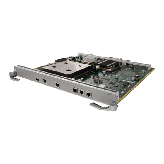
RMS-MODBUS01A User Manual 2 Overview Overview 2.1 Introduction The RMS-MODBUS01A card provides an RS485 networking solution for remote UPS management. Table 2-1 Basic specifications of the RMS-MODBUS01A card Model Appearance Description RMS-MODBUS01A Applicable models: UPS2000-G-(6 kVA–20 kVA) and UPS2000-A-(6 kVA–10 kVA) series... - Page 8 RMS-MODBUS01A User Manual 2 Overview Table 2-2 RMS-MODBUS01A card functions Function Description Provides a DIP switch for selecting an Supports the Modbus protocol by RS485 communications protocol. setting the DIP switch. Provides a DIP switch for selecting a The two-wire or four-wire system can two-wire or four-wire system.
-
Page 9: Function Description
● The product 02354GLU does not support the YDN protocol. Figure 3-1 RJ45 ports Table 3-1 RJ45 pins Pin No. Signal Four-wire system: RS485TX+ Two-wire system: A Four-wire system: RS485TX- Two-wire system: B None RS485RX+ RS485RX- Issue 05 (2021-11-18) Copyright © Huawei Technologies Co., Ltd. -
Page 10: Dip Switch
S1 and S2 are respectively a functional DIP switch and an 8-bit address DIP switch for the RS485 port. Figure 3-2 DIP switches 3.2.1.1 Functional DIP Switch S1 Figure 3-3 RS485 functional DIP switch S1 Issue 05 (2021-11-18) Copyright © Huawei Technologies Co., Ltd. -
Page 11: Address Dip Switch S2
By default, the RS485 DIP switch is connected to pins 1 and 2 in two-wire mode and to pins 1, 2, 4, and 5 in four-wire mode. 3.2.1.2 Address DIP Switch S2 Modbus Protocol Issue 05 (2021-11-18) Copyright © Huawei Technologies Co., Ltd. - Page 12 485_ADDR7 OFF: 1 You can use the binary method to set the DIP switch. Table 3-4 Mapping between addresses and toggle switches Addre DIP1 DIP2 DIP3 DIP4 DIP5 DIP6 DIP7 DIP8 Issue 05 (2021-11-18) Copyright © Huawei Technologies Co., Ltd.
- Page 13 DIP5 DIP6 DIP7 DIP8 NO TE The preceding table provides the methods for setting addresses 1–32. For details about how to set addresses 33–247, see the binary DIP switch setting rules. Issue 05 (2021-11-18) Copyright © Huawei Technologies Co., Ltd.
- Page 14 ON: 0 485_ADDR3 OFF: 1 ON: 0 ON: 0 ON: 0 ON: 0 NO TE When you select the YDN-23 protocol, set the toggle switches 5–8 of the DIP switch to ON. Issue 05 (2021-11-18) Copyright © Huawei Technologies Co., Ltd.
-
Page 15: Dip Switch Setting (02354Glu)
3.2.2 DIP Switch Setting (02354GLU) S1 and S2 are address DIP switches for the RS485 port, and S3 and S4 are functional DIP switches for the RS485 port. Figure 3-5 DIP switches Issue 05 (2021-11-18) Copyright © Huawei Technologies Co., Ltd. -
Page 16: Address Dip Switch
Table 3-8 Description of the RS485 address DIP switch S2 Switch No. Definition DIP Switch Setting Address DIP switch ON: 0 485_ADDR4 OFF: 1 Address DIP switch ON: 0 485_ADDR5 OFF: 1 Issue 05 (2021-11-18) Copyright © Huawei Technologies Co., Ltd. - Page 17 Table 3-9 Mapping between addresses and toggle switches Addre DIP1 DIP2 DIP3 DIP4 DIP1 DIP2 DIP3 DIP4 (S1) (S1) (S1) (S1) (S2) (S2) (S2) (S2) Issue 05 (2021-11-18) Copyright © Huawei Technologies Co., Ltd.
-
Page 18: Functional Dip Switch
Table 3-10 Description of the RS485 functional DIP switch S3 Switch No. Definition DIP Switch Remarks Setting Reserved ON: 0 Toggle switches 1, 2, and 3 form a 3- OFF: 1 Issue 05 (2021-11-18) Copyright © Huawei Technologies Co., Ltd. - Page 19 OFF: four-wire system status. system Toggle switch for selecting a two- wire or four-wire system CAN build-out ON: with a build- resistor toggle out resistor switch OFF: without a build-out resistor Issue 05 (2021-11-18) Copyright © Huawei Technologies Co., Ltd.
-
Page 20: Installation
User Manual 4 Installation Installation 4.1 Unpacking and Checking After the RMS-MODBUS01A card is delivered onsite, unpack the package and check as follows: ● Visually inspect the appearance for shipping damage. If any damage is found, notify the carrier immediately. -
Page 21: Installation Procedure
Step 3. Keep the cover properly for future use. Figure 4-1 Removing the optional card slot cover Step 3 Insert the RMS-MODBUS01A card into the optional card slot along guide rails, and tighten the screws, as shown in Figure 4-2. -
Page 22: Rms-Modbus01A Card Settings
RMS-MODBUS01A User Manual 4 Installation Figure 4-2 Inserting the RMS-MODBUS01A card into the optional card slot Step 4 Perform the following operations to set up a network, as shown in Figure 4-3. Connect the COM_1 port (the COM_2 port is used for cascading) on the RMS-... - Page 23 Communications address of the Modbus card. You can set it through the DIP switch on the Modbus card. ● Baud rate Baud rate of the Modbus card. You can set it through the DIP switch on the Modbus card. ----End Issue 05 (2021-11-18) Copyright © Huawei Technologies Co., Ltd.
- Page 24 RMS-MODBUS01A User Manual 4 Installation NO TE For details about how to commission the Modbus card, search for UPS2000-(6 kVA–20 kVA) Modbus Protocol Development Guide on https://support.huawei.com/. Issue 05 (2021-11-18) Copyright © Huawei Technologies Co., Ltd.
-
Page 25: Networking
● indicates the RMS-MODBUS01A card communications cable. 5.2 Parallel System Networking In a parallel UPS system, install a RMS-MODBUS01A card on one UPS, as shown Figure 5-2. Issue 05 (2021-11-18) Copyright © Huawei Technologies Co., Ltd. -
Page 26: Hybrid Networking
Figure 5-3 Hybrid networking NO TE In the hybrid network, a maximum of four UPSs can be connected in the parallel system. indicates the parallel cable, and indicates the RMS-MODBUS01A card communications cable. Issue 05 (2021-11-18) Copyright © Huawei Technologies Co., Ltd. -
Page 27: A Acronyms And Abbreviations
RMS-MODBUS01A User Manual A Acronyms and Abbreviations Acronyms and Abbreviations RJ45 Registered Jack 45 RS485 Recommended Standard 485 RS232 Recommended Standard 232 uninterruptible power system Issue 05 (2021-11-18) Copyright © Huawei Technologies Co., Ltd.
Need help?
Do you have a question about the RMS-MODBUS01A and is the answer not in the manual?
Questions and answers