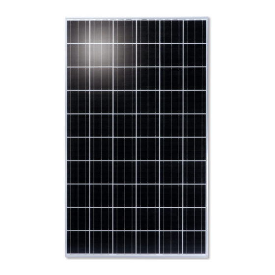
Kyocera KD Series Mounting Manual
Solar photovoltaic power modules
Hide thumbs
Also See for KD Series:
- Assembly and maintenance instructions (9 pages) ,
- Assembly and maintenance instructions (6 pages)
Advertisement
KKM-SM-0717-1
MOUNTING GUIDE
FOR THE
KD135GX-LFBS~KD245GX-LFB
OF
SOLAR PHOTOVOLTAIC POWER MODULES
Please read this guide carefully before installing the modules.
KYOCERA
2011.11.1
KD series modules may be attached to a support structure by the following methods. Detailed mounting method is
described in 'mounting table'. When installing modules in snowy area, an appropriate countermeasure has to be taken to
prevent possible damages to the lower side frame by slipping snow (e.g. attach supporting parts to the lowest modules.).
Any damage caused by snow or such countermeasure is not covered under warranty.
For optimal performance in all applications, clearance between the module frame and the mounting surface is required to
allow cooler ambient air to circulate around the back of the module and to avoid the module and / or wiring damage.
The minimum spacing of 2" (50 mm) is required between PV module and the mounting surface around the perimeter of PV
module. There should also be a clearance of at least .13" (3.2 mm) between the individual modules to allow heat-related
expansion.
BOLTING: Utilizing 5/16" or 8 mm steel hardware structure through the existing .35" (9 mm) diameter mounting holes in the
module frame and then through KD series modules mounting holes on the support structure.
Tighten the screws with adequate torque (usually 132 in-lb).
Support structure should have enough strength to keep the mounting span.
Refer to the below table for the position of PV module mounting holes.
CLAMPING: Fasten modules firmly with the clamps which must not be deformed by wind load or snow load, nor cause the
module fall off by using torque values specified by structure manufacturers.
Minimum 40mm clamping width, and minimum 9mm overlap onto frame are necessary.
Clamps also must not shade the sunlight incidence on glass surface.
Clamp material must be either stainless steel or anodized aluminum.
Support structure should have enough strength to keep the mounting span.
Refer to the below table for the permissible clamping range.
Advertisement
Table of Contents

Summary of Contents for Kyocera KD Series
- Page 1 KYOCERA 2011.11.1 KD series modules may be attached to a support structure by the following methods. Detailed mounting method is described in ‘mounting table’. When installing modules in snowy area, an appropriate countermeasure has to be taken to prevent possible damages to the lower side frame by slipping snow (e.g. attach supporting parts to the lowest modules.).
- Page 2 KKM-SM-0717-1 Mounting table-1 KD235GX-LFB KD240GX-LFB KD245GX-LFB Long side Bolting 281mm 1100mm 100mm 100mm 100mm 100mm Top down clamp : Permissible clamping range 281mm 1100mm...
- Page 3 KKM-SM-0717-1 Mounting table-2 KD215GX-LFBS KD220GX-LFBS Long Side Short Side Bolting 278.5mm 278.5mm 943mm 943mm 100mm 100mm 100mm 100mm 100mm 100mm 100mm 100mm 278.5mm 278.5mm 943mm 943mm 150mm 150mm 150mm 150mm Top Down 100mm 200mm 100mm 200mm Clamp Permissible clamping range 278.5mm 278.5mm 943mm...
- Page 4 KKM-SM-0717-1 Mounting table-3 KD135GX-LFBS KD140GX-LFBS Long Side Short Side Bolting 278.5mm 278.5mm 943mm 943mm 100mm 100mm 100mm 100mm 278.5mm 278.5mm 943mm 943mm 150mm 150mm 150mm 150mm Top Down Clamp 200mm 200mm Permissible clamping range 278.5mm 278.5mm 943mm 943mm 200mm 200mm 278.5mm 278.5mm 943mm...


Need help?
Do you have a question about the KD Series and is the answer not in the manual?
Questions and answers