Table of Contents
Advertisement
Quick Links
Advertisement
Table of Contents

Related Manuals for Doorentryonline DEO-SR2

Summary of Contents for Doorentryonline DEO-SR2
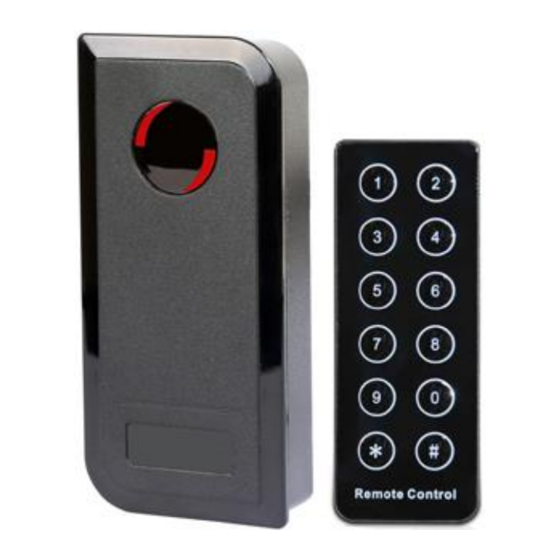
- Page 1 DEO-SR2 Proximity & Wiegand Card Reader with Remote Control User Manual...
-
Page 2: Specifications
INTRODUCTION The SR2 is a compact, weather resistant multi-function card reader that can be used as a standalone programmable access control card reader as well as a Wiegand output card reader providing proximity entry for up to 1000 users, (998 common users and 2 panic users) PIN access is also possible via the remote control unit for the Administrator and all user data can be transferred from one unit to another within 3 minutes (Maximum connection is 10 units) It reads both EM &... -
Page 3: Package Contents
Package Contents SR2 Card Reader Infrared Remote Control Manager Cards & 10 user cards or key fobs Diode IN4004 (For relay circuit protection) Self Tapping Screws: 3*25mm Wall Anchors Screw Driver... -
Page 4: Installation
INSTALLATION Remove the back cover from the unit Drill 2 holes(A,C) on the wall for the screws and one hole for the cable Knock the supplied rubber bungs to the screw holes(A,C) Fix the back cover firmly on the wall with 4 flat head screws ... -
Page 5: Connection Diagram Examples
Connection Diagram Examples Common power supply for magnetic lock (Fail open – power to lock) Common power supply for lock release (Fail secure – power to unlock) Common power supply for auto gate controller (using Normally Open contact) Attention: Install a 1N4004 or equivalent diode across the locking device when using a common power supply to prevent any back E.M.F as the reader might damage. - Page 6 Connection to standard Wiegand controller or PC access control system AC8001/2 Set Operation Mode – Stand-alone or Wiegand (Default is stand-alone) Programming Step Remote Control Operation 1. Enter Program Mode * (Master Code) # 2. Stand-alone Operation 72 # is factory default for stand-alone 3.
- Page 7 PROGRAMMING Programming will vary depending on access confirguration. Follow the instructions according to your access configuration General Programming Information – Two ways Remote Control: Please use the Infrared Remote Control to program the Reader. The infrared receiver head is near the LED, so when you program the reader, please direct the Remote Control to the LED User ID number: Assign a user ID to the access card in order to track it.
- Page 8 Set Operation Mode – Stand-alone or Wiegand (Default is stand-alone) Programming Step Remote Control Operation 1. Enter Program Mode * (Master Code) # 2. Stand-alone Operation 72 # is factory default for stand-alone 3. Wiegand Reader Operation 73 # 4. Exit Program Mode Set User Data Transfer Via the Remote Control Programming Step Remote Control Operation...
- Page 9 Delete User Cards Via the Remote Control Programming Step Remote Control Operation 1. Enter Program Mode * (Master Code) # 2. Delete Card: By read card 2 (Present Card) # Repeat Step 2 for additional user cards before pressing the 3.
- Page 10 Set Audible and Visual Response Via the Remote Control Programming Step Remote Control Operation 1. Enter Program Mode * (Master Code) # 2. Control LED OFF = 70 # ON = 71 # OFF = 74 # ON = 75 # 3.
-
Page 11: Reset Procedure
Reset Procedure Reset Alarm: The alarm will sound for 3 minutes. To reset, present a valid user card or enter * (Master Code) # via the remote control Reset to Factory Default: To reset to factory default, power off, press the Exit Button or short circuit the Black (GND) and Yellow (Open) wires, and then power on, there will be two bleeps, and the LED light will turn orange, keep this condition until you hear a long bleep after 10 seconds. - Page 12 Anti Tamper Alarm The SR2’s alarm trigger is activated by an LDR (Light Dependant Resistor) which is located to the top side of the unit as illustrated below The alarm function is designed as an ‘Anti-Theft’ facility. Forceful removal of the installed keypad or a sudden change in light source will trigger the keypad to bleep constantly.
Need help?
Do you have a question about the DEO-SR2 and is the answer not in the manual?
Questions and answers