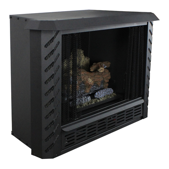
Ashley AGVF340 Owner’s Instruction And Operation Manual
Hide thumbs
Also See for AGVF340:
- Installation and operating manual (40 pages) ,
- Installation and operating manual (37 pages) ,
- Installation and operating manual (37 pages)
Table of Contents
Advertisement
Quick Links
Owner's Instruction and Operation Manual
Model Number:
AGVF340
Report Number: 21-721
Certified for installations in the USA
Approved for installation in mobile homes
MAY BE INSTALLED IN A SOLID FUEL BURNING FIREPLACE, AS A FREESTANDING FIREPLACE, AS A ZERO
CLEARANCE FIREPLACE OR WITH AN OPTIONAL WOODEN SURROUND
* All Pictures In This Manual Are For Illustrative Purposes Only. Actual Product May Vary.
Save These Instructions In A Safe Place For Future Reference.
Failure to follow safety warnings exactly could result in serious injury, death, or property damage.
Do not store or use gasoline or other flammable vapors and liquids in the vicinity of this or any other appliance.
WHAT TO DO IF YOU SMELL GAS:
•
Do not try to light any appliance.
•
Do not touch any electrical switch; do not use any phone in your building.
•
Leave the building immediately.
•
Immediately call your gas supplier from a neighbor's phone. Follow the gas supplier's instructions.
•
If you cannot reach your gas supplier, call the fire department.
Installation and service must be performed by a qualified installer, service agency or the gas supplier.
Please read this manual BEFORE
installing and operating this unit.
INSTALLER: Leave this manual with the appliance.
CONSUMER: Retain this manual for future reference.
THIS MANUAL IS SUBJECT TO CHANGE WITHOUT NOTICE.
© 2020 United States Stove Company, 227 Industrial Park Rd., South Pittsburg, TN 37380
WARNING:
FIRE OR EXPLOSION HAZARD
CALIFORNIA PROPOSITION 65 WARNING:
This product can expose you to chemicals including carbon
monoxide, which is known to the State of California to cause
cancer, birth defects, and/or other reproductive harm. For
more information, go to
852372M-3605K
www.P65warnings.ca.gov
Ph. 800-750-2723
Advertisement
Table of Contents

Subscribe to Our Youtube Channel
Related Manuals for Ashley AGVF340


Summary of Contents for Ashley AGVF340
- Page 1 Owner’s Instruction and Operation Manual Model Number: AGVF340 Report Number: 21-721 Certified for installations in the USA Approved for installation in mobile homes MAY BE INSTALLED IN A SOLID FUEL BURNING FIREPLACE, AS A FREESTANDING FIREPLACE, AS A ZERO CLEARANCE FIREPLACE OR WITH AN OPTIONAL WOODEN SURROUND * All Pictures In This Manual Are For Illustrative Purposes Only.
-
Page 2: Code Approval
CERTIFICATIONS CODE APPROVAL This is an unvented gas-fired heater. It uses air (oxygen) from room in which it is installed. Provisions for adequate combustion and ventilation air must be provided. This appliance has been tested and found to comply with the established standards for unvented gas-fired heater in the USA as follows: STANDARDS •... -
Page 3: Installation Checklist
INSTALLATION CHECKLIST Your Gas Stove should be installed by a qualified installer only. An NFI qualified Installer can be found at www.nficertified.org/public/find-an-nfi-pro/ CUSTOMER SERVICE 1-800-750-2723 ext 5050 Text to 423-301-5624 Email to: Customerservice@usstove.com COMMISSIONING CHECKLIST This Checklist is to be completed in full by the qualified person who installs this unit. Keep this page for future reference. -
Page 4: Massachusetts Residents Only
MASSACHUSETTS RESIDENTS ONLY REQUIREMENTS FOR THE operated carbon monoxide detector with an alarm shall be installed. COMMONWEALTH OF MASSACHUSETTS APPROVED CARBON MONOXIDE This product must be installed by a licensed DETECTORS plumber or gas fitter when installed within the Each carbon monoxide detector as required in Commonwealth of Massachusetts. -
Page 5: Safety Information
MASSACHUSETTS RESIDENTS ONLY • Detailed instructions for the installation of the • The referenced “special venting system” venting system design or the venting system instructions shall be included with the appliance components or equipment installation instructions; and • A complete parts list for the venting system •... - Page 6 SAFETY INFORMATION even though no odor exists. Make certain you read 6. This heater shall not be installed in unusually and understand all warnings. Keep this manual for tight construction unless provisions are provided reference. It is your guide to the safe and proper for adequate combustion and ventilation air operation of this stove.
- Page 7 SAFETY INFORMATION 19. Do not use this heater for burning trash or WARNING: cooking. Never place matches, paper, garbage ANY OUTSIDE AIR DUCTS AND/OR ASH DUMPS or any other material on top of logs or into the FIREPLACE SHALL PERMANENTLY flames.
-
Page 8: Installation Information
INSTALLATION INFORMATION CLEARANCES WARNING: CONNECTION DIRECTLY TO AN UNREGULATED LP TANK CAN CAUSE AN EXPLOSION. We recommend that our gas hearth products be installed Normal gas connection is 3/8” N.P.T. made at the and serviced by profes- left rear side of the appliance (facing front of the sionals who are certi ed in appliance). - Page 9 INSTALLATION INFORMATION • To avoid irreparable damage to the heater or section of the base between rear burner tube personal injury, matches, paper, garbage or any and front burner pan. other material must not be placed or thrown on 3. Place Left Top Middle log #5 on pins located on top of logs or into flames.
-
Page 10: Gas Pressure Check
INSTALLATION INFORMATION bleed out the air in the gas lines. Do this by holding the control knob and turning the knob to the “Pilot” position for about 30 seconds. To check the regulator pressure, remove the pressure tag plug at the left side of the regulator facing the heater. -
Page 11: What To Do If You Smell Gas
OPERATING INSTRUCTIONS Before operating this appliance, proceed through to replace any part of the control system and the following checklist. any gas control which has been under water. Read and understand these instructions before operating this appliance. WARNING: 2. Check that there are no gas leaks. If you smell FIREPLACE SCREENS MUST BE CLOSED WHILE gas do not attempt to light this appliance. -
Page 12: To Turn Off Gas To Appliance
OPERATING INSTRUCTIONS TO TURN OFF GAS TO APPLIANCE release the control knob and it will pop back up. The pilot should remain lit. If the pilot goes out, repeat steps 1 through 9. CAUTION: • If knob does not pop up when released, stop and DO NOT TRY TO ADJUST HEATING LEVELS BY immediately call your service technician or gas USING MANUAL SHUTOFF VALVE. -
Page 13: Manual Lighting Procedure
OPERATING INSTRUCTIONS IMPORTANT: ALWAYS OPERATE APPLIANCE COMPLETELY “ON” OR COMPLETELY “OFF” POSITIONS. NEVER USE THE HEATER AT A SETTING BETWEEN THESE POSITIONS AS THIS CAN RESULT IN IMPROPER COMBUSTION AND EXCESSIVE CARBON MONOXIDE EMISSIONS. Thermocouple for LP MANUAL LIGHTING PROCEDURE Correct Pilot Flame Appearance If the pilot will not light using the piezo ignitor, you can light the pilot with a long neck lighter. -
Page 14: Optional Kits
OPTIONAL KITS AG34MK MANTEL KIT There are optional kits available for your stove. These are listed below: • Insert Fireplace Facade • Wooden Surround • Brick Panel Kit • Stainless Steel Kit For more information on these kits contact your local representative or appliance manufacture. -
Page 15: Zero Clearance Installation
INSTALLATION SOLID FUEL BURNING FIREPLACES CAUTION: INSTALLATION TRIM PANELS OR SURROUNDS SHALL NOT This model may be installed in a masonry fireplace. SEAL VENTILATION OPENINGS The figure below demonstrates the required FIREPLACE. dimensions. NOTE: See “Producing Adequate Air for Combustion ATTENTION: And Ventilation”... - Page 16 INSTALLATION ZERO CLEARANCE STANDOFF(S) The Manufacturers Trim Kit must be used for Zero Clearance Installation. See the “Insert Fireplace ASSEMBLY Facade Installation” section of this manual for NOTE: All Standoff must be attached to the fireplace installations. appliance before installing as a Zero Clearance appliance.
-
Page 17: Side View
INSTALLATION may rest on standoffs on top of the firebox. When 2. Ceiling Clearances: There minimum the firebox is installed over carpeting, vinyl tile, or clearance from the top of the unit to the ceiling any combustible material other than wood flooring, that must be as shown in the figures below. -
Page 18: Freestanding Installation
INSTALLATION for your fireplace from formal wall treatments with NOTE: marble and mantels, to rustic wood paneling, stone DIMENSIONSSHOWNARE or brick. Noncombustible materials used in this MINIMUMCLEARANCETO 1-1/2” COMBUSTIBLEWALL. installation such as slate, tile, marble, etc. must be at least 1/2” thick. IT IS IMPORTANT THAT BLACK FACE OF FIREPLACE NOT BE COVERED WITH ANY 7”... - Page 19 INSTALLATION WARNING: CAUTION: WHEN APPLIANCE INSTALLED DIRECTLY ON CARPETING, TILE OR OTHER THE INSTALLATION MUST CONFORM WITH COMBUSTIBLE MATERIAL, OTHER THAN LOCAL CODES OR IN ABSENCE OF LOCAL WOOD FLOORING, THE APPLIANCE SHALL CODES, WITH NATIONAL FUEL GAS CODE, BE INSTALLED ON A METAL OR WOOD PANEL ANSI Z223.1/NFPA54.
-
Page 20: Producing Adequate Air For Combustion And Ventilation
VENTILATION PRODUCING ADEQUATE AIR FOR NOTE: SOME AREAS IN THE UNITED STATES HAVE HIGHER REQUIREMENTS FOR CUBIC FEET PER COMBUSTION AND VENTILATION 1000 BTU/ HOUR INPUT. (EX. CINCINNATI, OHIO This section is for residential or manufactured CODES REQUIRE 70 CUBIC FEET). CHECK YOUR (mobile) installation. - Page 21 VENTILATION Determine the volume of the space (length x width x height). Length x Width x Height = _____________cu.ft.(volume of space) EXAMPLE: 20 ft.(Length) x 16 ft.(Width) x 8 ft.(ceiling Height)= 2560 cu. ft. (volume of space) If additional ventilation to adjoining room is supplied with grills or openings, add the volume of these rooms to the total volume of the space.
-
Page 22: Air For Combustion And Ventilation Inside Building
VENTILATION AIR FOR COMBUSTION AND AIR FOR COMBUSTION AND VENTILATION INSIDE BUILDING VENTILATION OUTDOORS This fresh air would come from an adjoining Provide extra fresh air by using ventilation grills or unconfined space. When venting to an adjoining ducts. You must provide two permanent openings: space, you must provide two permanent openings: one within 12”... -
Page 23: Wiring Diagram
WIRING DIAGRAM WHEN USED AS A HEATING APPLIANCE Note: Installation and repair should be done by a qualified service person. This heater should be HEAT OUTPUT inspected before use and at least annually by a When used as a ventless heater, flue damper of a qualified service person. -
Page 24: Maintenance
MAINTENANCE CLEANING use caution when removing. Lift each log by holding it carefully at each end. Use a vacuum • The appliance must be turned “Off” before cleaner to remove dust and loose particles from cleaning inside the firebox (burn area), make sure the base, logs and around the burner and ODS/ the pilot is “Off”... -
Page 25: Troubleshooting
TROUBLESHOOTING CAUTION: INSTALLATION AND REPAIR SHALL ONLY BE DONE BY A QUALIFIED SERVICE PERSON. THE FIREPLACE SHOULD BE INSPECTED BEFORE USE BY A QUALIFIED SERVICE PERSON. IT IS REQUIRED TO BE INSPECTED AT LEAST ONCE A YEAR BY A PROFESSIONAL SERVICE PERSON. WARNING: TURN OFF, UNPLUG HEATER AND LET COOL BEFORE SERVICING. - Page 26 TROUBLESHOOTING OBSERVED PROBLEM POSSIBLE CAUSE SOLUTION Control knob is not fully pressed in Press control knob completely Control knob not pressed in long After ODS/Pilot lights keep control enough knob pressed thirty (30) seconds Safety interlock system has been Wait one (1) minute for safety triggered (if equipped) interlock system to reset Manual shutoff valve not fully open...
- Page 27 TROUBLESHOOTING OBSERVED PROBLEM POSSIBLE CAUSE SOLUTION Heater produces a clinking/ This is common with most heaters. If Metal expands while heating or ticking noise just after noise is excessive, contact a qualified contracts while cooling burner is lit r shut off service person Heater burning vapors from paint, Ventilate room.
-
Page 28: Replacement Parts
REPLACEMENT PARTS Part # Description Upper Burner Orifices 81212.16 (Nat) #46 81212.2 Flex Tube Upper Burner Orifices 81212.20 89761 Piezo Ignitor (LP) #56 81202 Control Valve (LP) Lower Burner Orifices 81212.17 (NAT) #48 81198 Control Valve (NAT) Lower Burner Orifices 81212-6 Bottom Burner 81212.21...
Need help?
Do you have a question about the AGVF340 and is the answer not in the manual?
Questions and answers