
Related Manuals for BEHA LanTest 50


Summary of Contents for BEHA LanTest 50
- Page 1 BEHAcom ® Bedienungsanleitung Best.-Nr. 870150 Instrcution manual Cat. No 870150 Istruzioni d'uso N° d'ord. 870150 Manual de manejo N° de p. 870150 LanTest 50...
-
Page 2: Table Of Contents
Inhalt ....................Seite Allgemeines/ Einleitung/ Lieferumfang ..........3 Sicherheitsmaßnahmen ..............4 Bestimmungsgemäße Verwendung ..........5 Transport und Lagerung ..............5 Betriebsvorbereitung ................6 Stromversorgung ................6 Einlegen der Batterie................6 Durchführen von Messungen ............6 Bedienelemente und Anschlüsse ............6 Allgemeines zu Messungen ..............8 Durchführung von Messungen ............8 Wartung ....................17 Reinigung..................17 Batteriewechsel ................18 Technical Data ..................19... -
Page 3: Allgemeines/ Einleitung/ Lieferumfang
Hinweise zu beachten, können ernste oder lebensgefährliche Verletzungen bzw. Beschädigungen des Gerätes eintreten. Allgemeines/ Einleitung/ Lieferumfang Der BEHAcom LanTest 50 ist ein tragbares Kabeltestgerät und kann zum Prüfen von Kabeldurchgängen und Kabelbelegungen von Twisted Pair / 10Base-T (UTP/STP) und Thin Ethernet (BNC) verwendet werden. -
Page 4: Sicherheitsmaßnahmen
Sicherheitsmaßnahmen Bei sämtlichen Arbeiten müssen die jeweils gültigen Unfallverhütungsvor- schriften der gewerblichen Berufsgenossenschaften für elektrische Anlagen und Betriebsmittel beachtet werden. Messungen in gefährlicher Nähe elektrischer Anlagen sind nur nach Anwei- sung einer verantwortlichen Elektrofachkraft und nicht alleine durchzuführen. Versuchen Sie nie eine Batteriezelle zu zerlegen! Das Elektrolyt in dem Akku ist höchst alkalisch. -
Page 5: Bestimmungsgemäße Verwendung
Vermeiden Sie eine Erwärmung der Geräte durch direkte Sonneneinstrah- lung. Nur so kann eine einwandfreie Funktion und eine lange Lebensdauer gewährleistet werden. Bestimmungsgemäße Verwendung Das Gerät darf nur unter den Bedingungen und für die Zwecke eingesetzt werden, für die es konstruiert wurde. Hierzu sind besonders die Sicherheits- hinweise (Kapitel 2.0), die Technischen Daten mit den Umgebungsbedin- gungen (Kapitel 7.0) und die Verwendung in trockener Umgebung zu beach- ten. -
Page 6: Betriebsvorbereitung
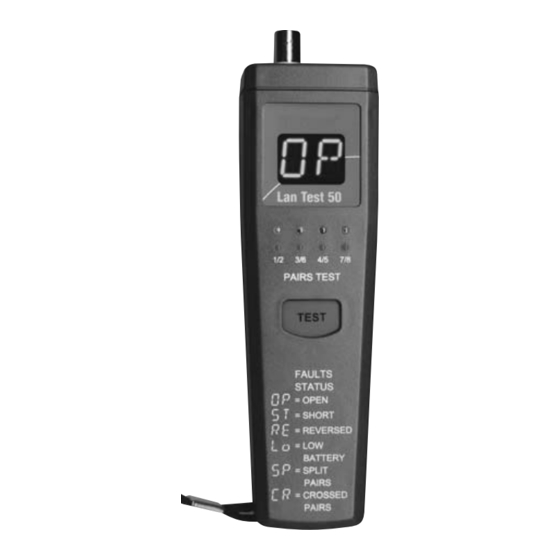
Batteriefach einsetzen. Den Batteriefachdeckel wieder aufsetzen und arretieren. Durchführen von Messungen Bedienelemente und Anschlüsse RJ45 PAIRS TEST TEST FAULTS STATUS = OPEN = SHORT = REVERSED = LOW BATTERY = SPLIT PAIRS = CROSSED PAIRS Bild Lantest 50 -01... - Page 7 Gerätevorderseite 1) Taste "TEST", zum Starten der Messung Nach beendeter Messung schaltet sich das Prüfgerät automatisch wieder aus. 2) 4 rote LED, für Fehleranzeige 3) 4 grüne LED, für Gutanzeige 4) 14-Segementanzeige, für Fehlercode Anschlussfeld 5) BNC-Testanschlussbuchse 6) RJ45-Testanschlussbuchse Geräterückseite: 7) Batteriefachdeckel 8) Kupplung, RJ45-RJ45 9) Kodierstecker "1"...
-
Page 8: Allgemeines Zu Messungen
Allgemeines zu Messungen Bei jeder Messung müssen die Sicherheitshinweise unter Punkt 2.0 beachtet wer- den. Das Meßgerät nie an ein aktives Netzwerk anschließen. Dies kann zu einer Störung des Netzbetriebs oder zu Beschädigungen des Meßgerätes führen. Der Versuch, einen anderen Steckverbinder als einen RJ45 (wie etwa einen RJ11 (Telefon)-Steckverbinder) in eine RJ45-Buchse einzustecken, kann zur permanenten Beschädigung der Buchse führen. - Page 9 Die nebenstehende Zeichnung zeigt die Zuordnung der Paare nach EN 50173 1 2 3 4 5 6 7 8 Bild 5-02 Verbinden Sie die eine Seite des zu prüfenden Kabel mit der RJ45-Testan- schlussbuchse (6). Verbinden Sie die andere Seite des zu prüfenden Kabel mit der RJ45-Test- anschlussbuchse des Kodiersteckers (9b).
- Page 10 = SPLIT PAIRS = CROSSED PAIRS Bild Lantest 50-02 Durch Drücken der Taste "TEST" (1) wird die Prüfung bzw. Messung gestar- tet. Das Gerät scannt nun die Schirmung und jede einzelne Leitung nacheinan- der ab. Ist das Kabel in Ordnung erscheint zuerst in der 14-Segmentanzeige (4) für die Abschirmung die Anzeige "SH"...
- Page 11 Verdrahtung Anzeige 1/2 3/6 4/5 7/8 1/2 3/6 4/5 7/8 Bild 5-04 Bild5-05 Die Schirmung (Sc) ist in Ordnung. Verdrahtung Anzeige 1/2 3/6 4/5 7/8 1/2 3/6 4/5 7/8 Bild 5-06 Bild 5-07...
- Page 12 Verdrahtung Verdrahtung Bild 5-08 Bild 5-10 Avoin: Hier ist das Paar 1-2 unterbro- chen. Anzeige Anzeige 1/2 3/6 4/5 7/8 1/2 3/6 4/5 7/8 Bild 5-11 Bild 5-09 Offen – gekreuzte Drähte: Zwei Unterbrechungen deuten meist auf eine gekreuztets Paar hin: Der Draht 2 des Paares 1-2 ist mit dem Draht 3 des Paares 3-6 gekreuzt.
- Page 13 Verdrahtung Verdrahtung Bild 5-12 Bild 5-14 Anzeige Anzeige 1/2 3/6 4/5 7/8 1/2 3/6 4/5 7/8 Bild 5-13 Bild 5-15 Kurzschluss: Hier ist das Paar 3-6 Vertauschtes Paar: Die Drähte 4 und 5 kurzgeschlossen sind gekreuzt, d.h. die Polarität des Paares 4-5 ist gedreht...
- Page 14 Verdrahtung Verdrahtung Bild 5-16 Bild 5-18 Anzeige Anzeige 1/2 3/6 4/5 7/8 1/2 3/6 4/5 7/8 Bild 5-19 Bild 5-17 Geteilte Paare – Split Pairs: Gekreuztes Paar: Paar 1-2 wurde mit Geteilte Paare treten auf, wenn ein dem Paar 3-6 gekreuzt Draht eines Paares versehentlich mit einem Drahtes eines anderen Paares verdrillt ist...
- Page 15 Der gleiche Fehlercode erscheint, wenn z.B. die Leitung 6 und 7 kurzge- schlossen sind Dieser Verdrahtungsfehler wird durch eine vereinfachte NEXT-Messungen festgestellt. Das Nahnebensprechen (NEXT; auch Querdämpfung) definiert das Übersprechen bzw. das Übertreten von Signalenergie zwischen den Ka- belpaaren in einem Datenkabel. Dabei erzeugt das elektromagnetische Feld des Nutzsignals eines Adernpaares in einem benachbarten Adernpaar ein Störsignal.
- Page 16 Montierte Abschlusswiderstände werden ebenfalls als Kurzschluss erkannt und angezeigt. Nach beendeter Messung schaltet sich das Prüfgerät automatisch wieder aus. 5.3.3 Leitungssuchfunktion Das Gerät kann auch zum Auffinden und der Zuordnung von nicht gekennzeichne- ten RJ45-Anschlüssen eingesetzt werden. Das Gerät erkennt den Kodierstecker, welcher das andere Ende der Kabelstrecke abschliesst.
-
Page 17: Wartung
Wartung Der BEHAcom LanTest 50 benötigt bei einem Betrieb gemäß der Bedienungsan- leitung keine besondere Wartung. Sollten Sie im praktischen Alltag Anwendungs- probleme haben, steht Ihnen unter der Hotline (Rufnummer 0 76 84 / 80 09-429) unser Beratungs-Service kostenlos zur Verfügung Reinigung Sollte das Gerät durch den täglichen Gebrauch schmutzig geworden sein, kann... -
Page 18: Batteriewechsel
Batteriewechsel Wenn am BEHAcom LanTest 50 in der 14-Segmentanzeige der Fehlercode "Lo" er- scheint, muss die Batterie ausgewechselt werden. Vor dem Batteriewechsel muß das Gerät von allen angeschlossenen Stromkreisen getrennt werden. Es müssen hierbei unbedingt die unter Kapitel 2.0 beschriebenen Hinweise bzgl. -
Page 19: Technical Data
Technical Data (gültig für 23 °C ± 5 °C, bei weniger als 70 % relativer Feuchte). Anzeige ..........14 Segmente für Fehlercode Rot/Grün für Gut-/Schlechtbewertung Anschluss ..........RJ45 und BNC min. Leitungslänge ........ca. 1,2 m max. Leitungslänge ........ca. 150 m Fremdspannungsfestigkeit......max. 56 V Stromversorgung........9-V, IEC 6LR61 Automatische Geräteabschaltung nach dem Kabeltest Abmessungen (B x H x T): ......ca. -
Page 20: 24 Monate Garantie
24 Monate Garantie UNITEST Geräte unterliegen einer strengen Qualitätskontrolle. Sollten in der tägli- chen Praxis dennoch Fehler in der Funktion auftreten, so gewähren wir eine Ga- rantie von 12 Monaten (nur gültig mit Rechnung). Fabrikations- oder Materialfehler werden von uns kostenlos beseitigt, sofern das Gerät ohne Fremdeinwirkung defekt ist und es ungeöffnet an uns zurückgesandt wird. - Page 21 BEHAcom ® Bedienungsanleitung Best.-Nr. 870150 Instrcution manual Cat. No 870150 Istruzioni d'uso N° d'ord. 870150 Manual de manejo N° de p. 870150 LanTest 50...
- Page 22 Contents ....................Page General Information / Introduction /Scope of Supply ......23 Safety Measures................24 Appropriate Usage ................25 Transport and Storage ..............25 4 .0 Preparation for Operation ..............26 Operational Preparations ..............26 Inserting the battery ................26 Carrying out measurements ..............26 Operation Elements an Connections ..........26 General Information regarding Measurements ........28 Carrying out the Measurements ............28 5.3.2...
-
Page 23: General Information / Introduction /Scope Of Supply
General Information / Introduction / Scope of Supply The instrument BEHAcom LanTest 50 is a portable cable tester and can be used to test cable continuity and cable assignments of twisted pairs / 10Base-T (UTP/STP) and Thin Ethernet (BNC). -
Page 24: Safety Measures
Safety Measures The respective accident prevention regulations established by the professio- nal associations regarding Laser Radiation have to be strictly met for all tasks Measurements in dangerous proximity of electrical installations are only to be executed when instructed by a responsible electrical specialist, and never alone. -
Page 25: Appropriate Usage
Appropriate Usage The instrument may only be used under the conditions and purposes in com- pliance with the specification. For this reason, the Safety Measures section (Chapter 2.0), the technical data section including environmental conditions (Chapter 7.0) and the usage in dry environments have to be complied with, in particular. -
Page 26: Preparation For Operation
Replace the three casing screws and retighten them. Carrying out measurements Operation Elements an Connections RJ45 PAIRS TEST TEST FAULTS STATUS = OPEN = SHORT = REVERSED = LOW BATTERY = SPLIT PAIRS = CROSSED PAIRS Bild Lantest 50 -01... - Page 27 Instrument front 1) Press the "TEST" key to start the measurement After completion of the measurement, the test instrument switches off au- tomatically. 2) 4 red LEDs, for error indication 3) 4 green LEDs, for good indication 4) 14-sement display, for error code Connection panel 5) BNC test connection socket 6) RJ45 test connection socket...
-
Page 28: General Information Regarding Measurements
General Information regarding Measurements For any measurement, please observe the safety references indicated in section Never connect the measurement instrument to an active network. This can lead to network operation interference or to instrument damage. The socket may be permantently damaged, if the user tries to connect another plug connector to a RJ45 socket than a RJ45 plug (such as a RJ11 phone plug connector). - Page 29 The figure attached shows the pair assignment in compliance with EN 50173, 1 2 3 4 5 6 7 8 Figure 5-02 Pair Assignment Connect the one end of the cable under test with the RJ45 test connection socket (6). Connect the other end of the cable under test with the RJ45 test connec- tion socket of the coding plug (9b).
- Page 30 PAIRS TEST TEST FAULTS STATUS = OPEN = SHORT = REVERSED = LOW BATTERY = SPLIT PAIRS = CROSSED PAIRS Figure 5-03 (Instrument Connection) The test or measurement is started by pressing the ”TEST” key (1). Now, the instrument subsequently scans the shielding for each individual conductor.
- Page 31 Wiring Display Display 1/2 3/6 4/5 7/8 1/2 3/6 4/5 7/8 Figure 5-04 Figure5-05 The shielding (Sc) is in order. Wiring Display Display 1/2 3/6 4/5 7/8 1/2 3/6 4/5 7/8 Figure 5-06 Figure 5-07...
- Page 32 Wiring Display Wiring Display Figure 5-08 Figure 5-10 Display Display 1/2 3/6 4/5 7/8 1/2 3/6 4/5 7/8 Figure 5-09 Figure 5-11 Open: Here, the pair 1-2 is interrupted Open – crossed wires: two inter- ruptions mostly indicate a cros- sed pair: Wire 2 of pair 1-2 is cros- sed with wire 3 of pair 3-6.
- Page 33 Wiring Display Wiring Display Figure 5-12 Figure 5-14 Display Display 1/2 3/6 4/5 7/8 1/2 3/6 4/5 7/8 Figure 5-13 Figure 5-15 Short-circuit: here, pair 3-6 has a Exchanged pair: wires 4 and 5 are short-circuit. crossed, i.e. reverse polarity of pair 4-...
- Page 34 Wiring Display Wiring Display Figure 5-16 Figure 5-18 Display Display 1/2 3/6 4/5 7/8 1/2 3/6 4/5 7/8 Figure 5-17 Figure 5-19 Crossed pair: pair 1-2 has been crossed Split pairs: split pairs occur, if one wire with pair 3-6. of a pair is drilled by mistake with a wire of another pair.
-
Page 35: Checking Coax Cables (Bnc, Thin Ethernet)
The same error code appears, if e.g. cable 6 and 7 have a short-circuit. This wiring error is detected by a simplified NEXT measurement. The Near End Cross Talk (NEXT) (also horizontal attenuation) defines the side-to-side crosstalk or excess of signal energy between the cable pairs within a data cable. -
Page 36: Conductor Locating Function
5.3.3 Conductor Locating Function The instrument may also be used to locate and assign unlabelled RF45 connec- tions. The instrument recognises coding plugs terminating Plug-on the coding plug (9) on top of the adapter cable on the one side of the cable path to be chekked (e.g. -
Page 37: Battery Replacement
Battery Replacement If the Code "Lo" is illuminated on the instrument display, you have to proceed with the battery replacement. Prior any measurement, disconnect teh instrument from all circuits. The operator must comply with the references as described in section 2.0 regarding the handling of batteries Switch off the instrument via the slide switch (1). -
Page 38: Technical Data
Technical Data (gültig für 23 °C ± 5 °C, bei weniger als 70 % relativer Feuchte). Display ..........14 Segments for Errorcode, Red/green for good-/bad assesment Connection ........RJ45 and BNC min. Cablelenght......approx. 1,2 m max. Cablelenght ......approx. 150 m Fremdspannungsfestigkeit ....max. 56 V Power Supply ........9-V, IEC 6LR61 ............Auto-Power-Off after cable test Dimensions (W x H x D):....approx. - Page 39 BEHAcom ® Bedienungsanleitung Best.-Nr. 870150 Instrcution manual Cat. No 870150 istruzioni d'uso N° d'ord. 870150 Manual de manejo N° de p. 870150 LanTest 50...
- Page 40 Sommario ....................Pagina Nozioni generali/ Introduzione/ Contenuto della fornitura ....41 Provvedimenti di sicurezza ..............41 Uso consentito ..................42 Trasporto e immagazzinaggio............43 Preparativi all'esercizio..............43 Alimentazione di corrente ..............44 Inserimento della batteria ..............44 Esecuzione di misurazioni ..............44 Elementi di comando e collegamenti ..........44 Nozioni generali sulle misurazioni ............45 Esecuzione di misurazioni ..............46 5.3.1 Prova di cablaggio di coppie di coppie di...
-
Page 41: Nozioni Generali/ Introduzione/Contenuto Della Fornitura
Nozioni generali/ Introduzione/ Contenuto della fornitura Il BEHAcom LanTest 50 è un tester per cavi LAN di tipo portatile che può essere usato per la verifica di passaggi e di assegnazioni di cavi di tipo Twisted Pair / 10Base-T (UTP/STP) e Thin Ethernet (BNC). -
Page 42: Provvedimenti Di Sicurezza
Provvedimenti di sicurezza Durante ogni lavoro devono essere osservate le prescrizioni antinfortunisti- che vigenti degli enti antinfortunistici commerciali per impianti elettrici e mezzi di esercizio. Le misurazioni nelle dirette vicinanze di impianti elettrici devono essere ese- guite esclusivamente seguendo le istruzioni di un elettricista responsabile e non da soli o di propria iniziativa. -
Page 43: Uso Consentito
Uso consentito L'apparecchio deve essere usato solo nelle condizioni e per gli scopi per i quali è stato costruito. A tale riguardo sono da osservare in particolar modo le avvertenze di sicurezza (capitolo 2.0), i dati tecnici con le condizioni am- bientali (capitolo 7.0) e l'uso in luoghi asciutti. -
Page 44: Preparativi All'esercizio
Rimontare il coperchio del vano portabatterie ed arrestarlo. Esecuzione di misurazioni Elementi di comando e collegamenti RJ45 PAIRS TEST TEST FAULTS STATUS = OPEN = SHORT = REVERSED = LOW BATTERY = SPLIT PAIRS = CROSSED PAIRS Figura Lantest 50 -01... - Page 45 Lato anteriore dell'apparecchio 1) Tasto "TEST" per la partenza della misurazione Al termine della misurazione il tester si spegne automaticamente. 2) 4 LED rossi, per indicazione degli errori 3) 4 LED verdi, per indicazione di assenza errori 4) Indicatore a 14 segmenti, per codice errore Campo di collegamento 5) Boccola di collegamento per prova BNC 6) Boccola di collegamento per prova RJ45...
-
Page 46: Nozioni Generali Sulle Misurazioni
Nozioni generali sulle misurazioni Durante ogni misurazione devono essere osservate le avvertenze di sicurezza ri- portate al punto 2.0. Non collegare mai il tester ad una rete telematica attiva. Ciò può causare la distruzione dell'esercizio di rete o danneggiare il tester. Il tentativo di inserire un connettore diverso dal tipo RJ45 (come p.e. - Page 47 Il disegno a lato mostra l'assegnazione delle coppie secondo EN 50173 1 2 3 4 5 6 7 8 Figura 5-02 Collegate un lato del cavo da verificare con la boccola di collegamento prova RJ45 (6). Collegate l'altro lato del cavo da verificare con la boccola di collegamento prova RJ45 del connettore di codifica (9b).
- Page 48 PAIRS = CROSSED PAIRS Figura Lantest 50-02 Premendo il tasto "TEST" (1) viene fatta partire la verifica o la misurazione. L'apparecchio scansiona ora in successione la schermatura ed ogni singo- lo conduttore. Se il cavo è regolare allora nell'indicatore a 14 segmenti (4) compare dapprima, per la schermatura, l'indicazione "SH"...
- Page 49 Cablaggio Indicazione 1/2 3/6 4/5 7/8 1/2 3/6 4/5 7/8 Figura 5-04 Figura 5-05 La schermatura (Sc) è regolare. Cablaggio Indicazione 1/2 3/6 4/5 7/8 1/2 3/6 4/5 7/8 Figura 5-06 Figura 5-07...
- Page 50 Cablaggio Cablaggio Figura 5-08 Figura 5-10 Indicazione Indicazione 1/2 3/6 4/5 7/8 1/2 3/6 4/5 7/8 Figura 5-09 Figura 5-11 Aperto: Qui è interrotta la coppia di cavi 1-2. Aperto – cavi incrociati: Due inter- ruzioni significano solitamente una coppia di cavi incrociata: Il filo 2 della coppia 1-2 è...
- Page 51 Cablaggio Cablaggio Figura 5-12 Figura 5-14 Indicazione Indicazione 1/2 3/6 4/5 7/8 1/2 3/6 4/5 7/8 Figura 5-13 Figura 5-15 Cortocircuito: Qui è cortocircuitata la Coppia scambiata: I fili 4 e 5 sono in- coppia di cavi 3-6. crociati, vale a dire la polarità della coppia 4-5 è...
- Page 52 Cablaggio Cablaggio Figura 5-16 Figura 5-18 Indicazione Indicazione 1/2 3/6 4/5 7/8 1/2 3/6 4/5 7/8 Figura 5-17 Figura 5-19 Coppia incrociata: La coppia 1-2 è stata Coppie separate - Split Pairs: incrociata con la coppia 3-6 Coppie separate si presentano quando un filo di una coppia viene trefolato ac- cidentalmente con un filo di un'altra coppia.
- Page 53 Lo stesso codice errore compare se p.e. i conduttori 6 e 7 sono cortocircui- tati Questo errore di cablaggio viene determinato tramite misurazioni NEXT sem- plificate. La reazione ravvicinata (NEXT; o anche oscurazione trasversale) de- finisce la sovramodulazione o l'eccesso di energia di segnale fra coppie di cavi all'interno di un cavo dati.
-
Page 54: Manutenzione
Manutenzione Se usato come indicato nelle istruzioni d'uso, il BEHAcom LanTest 50 non richie- de una particolare manutenzione. Se durante l'uso quotidiano dovessero presen- tarsi degli inconvenienti, potete contattare il nostro servizio di assistenza alla hot-... -
Page 55: Pulizia
è completamente asciugato. Sostituzione della batteria Se nell'indicatore a 14 segmenti del BEHAcom LanTest 50 compare il codice di errore "Lo", significa che la batteria deve essere sostituita. Prima di sostituire la batteria l'apparecchio deve essere staccato da qualsiasi circuito elettrico. -
Page 56: Dati Tecnici
Dati tecnici (validi per una temperatura di 23 °C ± 5 °C, con umidità relativa minore di 70 %). Indicazione..........14 segmenti per codice errore Rosso/Verde per valutazione bene/male Attacco............RJ45 e BNC Lunghezza conduttore min.....ca. 1,2 m Lunghezza conduttore max.....ca. 150 m Resistenza alle tensioni esterne ....max. - Page 57 BEHAcom ® Bedienungsanleitung Best.-Nr. 870150 Instrcution manual Cat. No 870150 istruzioni d'uso N° d'ord. 870150 Manual de manejo N° de p. 870150 LanTest 50...
- Page 58 Generales/Introducción/Volumen de entrega ........59 Medidas de seguridad ..............60 Empleo para usos debidos ............61 Transporte y almacenamiento............61 Preparación para el servicio ..............62 Alimentación de corriente..............62 Colocación de la batería ..............62 Ejecución de mediciones ..............62 Elementos de mando y conexiones............62 Generales sobre medición ............64 Ejecución de mediciones ..............64 Mantenimiento ..................72...
-
Page 59: Generales/Introducción/Volumen De Entrega
Generales/Introducción/Volumen de entrega El BEHAcom LanTest 50 es un probador de cables portátil que puede ser emplea- do para controlar pasos de cables y ocupaciones de cables de Twisted Pair / 10Base-T (UTP/STP) y Thin Ethernet (BNC). -
Page 60: Medidas De Seguridad
Medidas de seguridad En todos los trabajos deben acatarse las respectivas prescripciones vigentes sobre prevención de accidentes de las correspondientes asociaciones profe- sionales para instalaciones eléctricas y medios de servicio. Las mediciones en las inmediaciones peligrosas de instalaciones eléctricas deben hacerse bajo instrucciones de un electricista responsable y nunca por sí... -
Page 61: Empleo Para Usos Debidos
Empleo para usos debidos El aparato debe ser empleado únicamente para los propósitos y bajo las con- diciones para los cuales ha sido construido. En esto deben acatarse espe- cialmente las instrucciones sobre seguridad (capítulo 2.0), las característi- cas técnicas con las condiciones ambientales (capítulo 7.0) y el empleo en ambientes secos. -
Page 62: Preparación Para El Servicio
Colocar y asegurar de nuevo la tapa del compartimiento de la batería. Ejecución de mediciones Elementos de mando y conexiones RJ45 PAIRS TEST TEST FAULTS STATUS = OPEN = SHORT = REVERSED = LOW BATTERY = SPLIT PAIRS = CROSSED PAIRS Imagen de Lantest 50 -01... - Page 63 Parte delantera 1) Tecla "TEST", para arrancar la medición Al terminar la medición se desconecta el aparato automáticamente. 2) 4 LED rojo, para indicación de fallo 3) 4 LED verde, para indicación de correcto 4) 14 indicaciones de segmentos, para código de fallo Campo de conexión 5) Casquillo BNC para conexión de prueba 6) Casquillo RJ45 para conexión de prueba...
-
Page 64: Generales Sobre Medición
Generales sobre medición En cada medición deben acatarse las observaciones sobre seguridad del punto 2.0. No conectar el medidor a una red activa. Eso puede ocasionar la destrucción del servicio de red o deterioros en el medidor. El intento de enchufar un enchufe distinto al RJ45 (como un RJ11 (enchufe de teléfono) en una caja RJ45 puede inducir a la avería permanente del cas- quillo. - Page 65 El diseño adjunto muestra la disposición de los pares según la norma EN 50173 1 2 3 4 5 6 7 8 Fig. 5-02 Conectar un extremo del cable a controlar con el casquillo de conexión RJ45 (6). Conectar el otro lado del cable a controlar con el casquillo de conexión de prueba RJ45 del enchufe codificador (9b).
- Page 66 PAIRS = CROSSED PAIRS Fig. Lantest 50-02 Oprimiendo el pulsador "TEST" (1) se arranca el control o medición. El aparato escanea ahora el blindaje y cada uno de los conductores, uno a continuación del otro. Si el cable está en orden aparece primeramente en el indicador de 14 segmentos (4) la indicación de "SH”...
- Page 67 Cableado Indicación 1/2 3/6 4/5 7/8 1/2 3/6 4/5 7/8 Fig. 5-04 Fig. 5-05 El blindaje (Sc) está correcto. Cableado Indicación 1/2 3/6 4/5 7/8 1/2 3/6 4/5 7/8 Fig. 5-06 Fig. 5-07...
- Page 68 Cableado Cableado Fig. 5-08 Fig. 5-10 Avoin: Aquí está interrumpido el par 1- Indicación Indicación 1/2 3/6 4/5 7/8 1/2 3/6 4/5 7/8 Fig. 5-11 Fig. 5-09 Hilos abiertos – cruzados: Mayor- mente, dos interrupciones sin in- dicio de un par cruzado: El hilo 2 del para 1-2 está...
- Page 69 Cableado Cableado Fig. 5-12 Fig. 5-14 Indicación Indicación 1/2 3/6 4/5 7/8 1/2 3/6 4/5 7/8 Fig. 5-13 Fig. 5-15 Cortocircuito: Aquí el par 3-6 tiene cor- Par invertido: Los hilos 4 y 5 están cru- tocircuito. zados, es decir, la polaridad del par 4- 5 está...
- Page 70 Cableado Cableado Bild 5-16 Bild 5-18 Indicación Indicación 1/2 3/6 4/5 7/8 1/2 3/6 4/5 7/8 Bild 5-19 Bild 5-17 Pares separados – Split Pairs: Par cruzado: El par 1-2 está cruzado Se presentan los pares separados don el par 3-6. cuando un hilo de un par cuando por error se tuerce un hilo con el de otro par.
- Page 71 El mismo código de error aparece cuando, por ejemplo, se cortocircuitan los conductores 6 y 7. Este error de cableado se determina por simple medición NEXT. La diafonía de proximidad (NEXT; también amortiguación transversal) define la diafonía o el desbordamiento de energía de señales entre los pares de cables de un cable de datos.
-
Page 72: Mantenimiento
Mantenimiento El BEHAcom LanTest 50 no requiere un mantenimiento especial, esto es, si el ser- vicio tiene lugar conforme al Manual de manejo. Si en la práctica diaria se hallaran problemas de aplicación, nuestro servicio de asesoramiento está gratuitamente a... -
Page 73: Limpieza
Cambio de batería Al apareces en el BEHAcom LanTest 50 en el indicador de 14 segmentos el códi- go de fallo "Lo" es necesario cambiar la batería. Antes de cambiar la batería debe cortarse el aparato de todos los circuitos de corriente conectados. -
Page 74: Características Técnicas
Características técnicas (válidas para 23 °C ± 5 °C, a menos del 70 % de humedad relativa). Indicación ..........14 segmentos para código de error rojo/verde para evaluación de correcto/in- correcto Conexión ..........RJ45 y BNC Longitud mín. de conductor....aprox. 1,2 m Longitud máx. -
Page 75: 24 Meses De Garantía
24 meses de garantía Los aparatos UNITEST están sometidos a un estricto control de calidad. Si, no obstante, en la práctica del trabajo diario se presentaran fallos en el funcionamien- to, nosotros otorgamos una garantía de 12 meses (válida exclusivamente con la factura). - Page 76 Certificat de Qualité • Certificado de calidad Die BEHA-Gruppe bestätigt The BEHA Group confirms Le groupe BEHA déclare que El grupo BEHA declara que el hiermit, dass das erworbene herein that the unit you have l´appareil auquel ce document producto adquirido ha sido ca- Produkt gemäß...
Need help?
Do you have a question about the LanTest 50 and is the answer not in the manual?
Questions and answers