Table of Contents
Advertisement
Quick Links
WARNING: If the information in this manual is not
followed exactly, a fire or explosion may result causing
property damage, personal injury or loss of life.
— Do not store or use gasoline or other flammable va-
pors and liquids in the vicinity of this or any other
appliance.
— WHAT TO DO IF YOU SMELL GAS
• Do not try to light any appliance.
• Do not touch any electrical switch; do not use any
phone in your building.
• Immediately call your gas supplier from a neighbor's
phone. Follow the gas supplier's instructions.
• If you cannot reach your gas supplier, call the fire
department.
— Installation and service must be performed by a quali-
fied installer, service agency or the gas supplier.
WARNING: This appliance is equipped for natural and
propane gas. Field conversion is not permitted other than
between natural or propane gases.
Questions, problems, missing parts? Before returning to your retailer, call
our customer service department at 1-866-573-0674, 8:00 am - 4:30 pm CST,
Monday through Friday or email contact@usaprocom.com
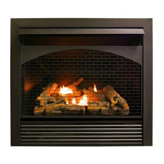
VENT-FREE GAS
FIREPLACE INSERT
OWNER'S OPERATION AND
INSTALLATION MANUAL
MODEL FBNSD32RT
This insert can be used in the following
mantel and fireplace systems:
FBNSD32RT-M-(MO,HC,U)
PFS
®
US
Advertisement
Table of Contents

Subscribe to Our Youtube Channel
Related Manuals for Procom FBNSD32RT


Summary of Contents for Procom FBNSD32RT
- Page 1 VENT-FREE GAS FIREPLACE INSERT OWNER’S OPERATION AND INSTALLATION MANUAL MODEL FBNSD32RT This insert can be used in the following mantel and fireplace systems: FBNSD32RT-M-(MO,HC,U) ® WARNING: If the information in this manual is not followed exactly, a fire or explosion may result causing property damage, personal injury or loss of life.
-
Page 2: Table Of Contents
TABLE OF CONTENTS Safety ............3 Operation ..........20 Specifications ..........5 Inspecting Burners........24 Qualified Installing Agency ......5 Care And Maintenance ......25 Product Features ........5 Troubleshooting ........26 Local Codes..........5 Replacement Parts ........29 Unpacking..........6 Parts ............ -
Page 3: Safety
SAFETY WARNING: Do not attempt to DANGER: Carbon monoxide access or change the setting of poisoning may lead to death! the fuel selection means. CARBON MONOXIDE POISONING: Early Access to and adjustment of signs of carbon monoxide poisoning resemble the fuel selection means must the flu, with headaches, dizziness or nausea. - Page 4 SAFETY 6. Do not run heater: WARNING: Do not place • Where flammable liquids or vapors are clothing or other flammable used or stored. material on or near the appliance. • Under dusty conditions. Never place any objects in the 7.
-
Page 5: Specifications
SPECIFICATIONS Model FBNSD32RT Gas Type Natural Gas Propane Gas Ignition Piezo Ignitor Piezo Ignitor Input Rating 32,000 Btu/Hr 32,000 Btu/Hr Pressure Regulator Setting 4" W.C. 9" W.C. Maximum 9.5" Maximum 14" Inlet Gas Pressure* (inches of water) (*for purposes of input adjustment) Minimum 5"... -
Page 6: Unpacking
UNPACKING 1. Remove top inner pack. 7. Remove log set by cutting plastic ties. 2. Tilt carton so that heater is upright. 8. Carefully unwrap log. 3. Remove protective side packaging. 9. Check for any shipping damage. If heater or log is damaged, promptly inform your 4. -
Page 7: Air For Combustion And Ventilation
AIR FOR COMBUSTION AND VENTILATION WARNING: This heater shall WARNING: This heater shall not be installed in a confined not be installed in a room or space or unusually tight construc- space unless the required vol- tion unless provisions are made ume of indoor combustion air for adequate combustion and is provided by the method de-... - Page 8 AIR FOR COMBUSTION AND VENTILATION VENTILATION AIR Ventilation Air From Inside Building This fresh air would come from an adjoining 1 and 2, Figure 2). You can also remove door unconfined space. When ventilating to an into adjoining room (see option 3, Figure 2). adjoining unconfined space, you must provide Follow the National Fuel Gas Code, ANSI two permanent openings: one within 12"...
-
Page 9: Installation
INSTALLATION IMPORTANT: Vent-free heaters add moisture NOTICE: This heater is intended to the air. Although this is beneficial, installing for use as supplemental heat. heater in rooms without enough ventilation air Use this heater along with your may cause mildew to form too much moisture. primary heating system. - Page 10 INSTALLATION GAS SELECTION Insert Gas Fitting Insert Gas Fitting This appliance is factory for Propane Gas for Natural Gas preset for propane gas. No changes are required for connecting to propane. Only a qualified installer or service techni- cian can perform gas selection and connecting to gas supply.
- Page 11 INSTALLATION Use only the cap supplied on the Brass regulator. Do not use an off the Fitting shelf pipe cap. This can damage the plunger. The supplied regula- tor cap is designed so it will not engage the unused gas type. 3.
- Page 12 INSTALLATION BUILT-IN FIREPLACE INSTALLATION WARNING: Do not allow any combustible materials to overlap the firebox front. WARNING: Do not allow combustible or noncombustible 3/4" Clearance to Facia materials to cover any necessary " Clearance to Sides, Back and Top openings like louvered slots. "...
- Page 13 INSTALLATION 3. Attach gas line to fireplace gas regulator. See Connecting to Gas Supply, page 14. 4. Check all gas connections for leaks. See Checking Gas Connections, page 16. " IMPORTANT: When finishing your firebox, combustible materials such as wall board, gypsum board, sheet rock, drywall, plywood, etc, must have 1/2"...
- Page 14 INSTALLATION CONNECTING TO GAS SUPPLY WARNING: A qualified ser- CAUTION: For propane gas, vice technician must connect never connect heater directly to the gas supply. This heater heater to gas supply. Follow all requires an external regulator local codes. (not supplied). Install the exter- WARNING: This appliance re- nal regulator between the heater quires a 3/8"...
- Page 15 INSTALLATION Apply pipe joint sealant lightly to male threads. shown in Figure 13. Pointing the vent down This will prevent excess sealant from going protects it from freezing rain or sleet. into pipe. Excess sealant in pipe could result For both gas types, install sediment trap in in clogged heater valves.
- Page 16 INSTALLATION CHECKING GAS CONNECTIONS 2. Pressurize supply piping system by either WARNING: Test all gas piping opening propane supply tank valve for and connections for leaks after propane gas or opening main gas valve installing or servicing. Correct located on or near gas meter for natural gas or using compressed air.
- Page 17 INSTALLATION 4. Check all joints from equipment shutoff 6. Light heater (see Lighting Instructions on valve to control valve (see Figure 16 or page 20). Check all other internal joints 17, page 16). Apply a noncorrosive leak for leaks. detection fluid to all joints. Bubbles form- 7.
- Page 18 INSTALLATION INSTALLING LOGS Each log is marked with a number. This WARNING: Failure to posi- number will help you to identify the logs when tion the parts in accordance installing. with these diagrams or failure After installing logs, add decorative cinders around the grate base, do not place any to use only parts specifically decorative cinders on logs or burner.
- Page 19 INSTALLATION INSTALLING BATTERIES Receiver and Remote Control CAUTION: Do not mix old and Batteries are required in both the Remote new batteries. Do not mix alka- Control (Transmitter) (2 AAA size) and Re- ceiver (4 AA size) (see Figure 23). line, standard (carbon - zinc), or Note: Be sure batteries are placed correctly.
-
Page 20: Operation
OPERATION FOR YOUR SAFETY READ BEFORE LIGHTING not use any phone in your building. WARNING: If you do not fol- • Immediately call your gas supplier low these instructions exactly, a from a neighbor’s phone. Follow the fire or explosion may result caus- gas supplier’s instructions. - Page 21 OPERATION 6. With control knob pressed in, push 9. Turn control knob counterclockwise down and release ignitor button. This to the ON position. The main burner will light pilot. The pilot is attached should light. to the burner. If needed, keep press- 10.
- Page 22 OPERATION REMOTE CONTROL SYSTEM Programming the Remote and Receiver Key Settings ON - Operates unit to on position, manually The remote and receiver must be “learned” to one another. operated solenoid ON. OFF - Operates unit to off position, manually To prepare the receiver box for learning, use a pen or small screwdriver to gently press operated solenoid OFF.
- Page 23 OPERATION Setting°F/°C Scale 2. Press and hold the SET key until the de- The factory setting for temperature is °F. To sired set temperature is reached. The LCD change this setting to °C, press the ON key screen set numbers will increase from 45° and the OFF key on the remote control at the to 99°...
-
Page 24: Inspecting Burners
INSPECTING BURNERS IMPORTANT: Owner’s should check pilot flame pattern and burner flame pattern often. Incorrect flame patterns indicate the need for cleaning (see Care and Maintenance, page 25) or service. WARNING: Only a qualified service person should service and repair heater. This includes maintenance requiring replacement or alteration of components. -
Page 25: Care And Maintenance
CARE AND MAINTENANCE WARNING: Turn off heater and let cool before servicing. CAUTION: You must keep control areas, burner, and circulating air passageways of heater clean. Inspect these areas of heater before each use. Have heater inspected yearly by a qualified service techni- cian. -
Page 26: Troubleshooting
CARE AND MAINTENANCE CABINET Air Passageways Exterior Use a vacuum cleaner or pressurized air to • Use a soft cloth dampened with a mild soap clean. and water mixture. • Wipe the cabinet to remove dust. LOGS • If you remove logs for cleaning, refer to Installing Logs, page 18, to properly replace logs. •... - Page 27 TROUBLESHOOTING The entire gas delivery piping including connec- the correct flame pattern as illustrated on page tions inside the heater should be leak tested by 22. All flame patterns should be safely inside the the qualified installer. After leak testing the quali- product.
- Page 28 TROUBLESHOOTING Problem Possible Cause Corrective Action Burner(s) does not light 1. Burner orifice is clogged. 1. Clean burner orifice (see after ODS/pilot is lit Care and Maintenance, page 25). 2. Inlet gas pressure is too low. 2. Contact local gas supplier. 3.
-
Page 29: Replacement Parts
TROUBLESHOOTING Problem Possible Cause Corrective Action Heater produces a click- 1. Metal is expanding while 1. This is common with most ing/ticking noise just after heating or contracting while heaters. If noise is exces- burner is lit or shut off. cooling. -
Page 30: Parts
PARTS MODEL FBNSD32RT www.usaprocom.com 200241-01E... -
Page 31: Service Hints
When calling, please have your model and serial numbers of your heater ready. ACCESSORIES Purchase these heater accessories from your local dealer. If they can not supply these acces- sories, contact ProCom Heating, Inc. at 1-866-573-0674 for information. EQUIPMENT SHUTOFF VALVE OPTIONAL FAN KIT - FIB100 For all models. -
Page 32: Warranty
We make no other warranty, expressed or implied. NEW PRODUCTS Standard Warranty: ProCom Heating, Inc. warrants this product to be free from defects in materials and components for ONE (1) year from the date of first purchase, provided that the product has been properly installed by a qualified installer in accordance with all local codes and instructions furnished with the unit, operated and maintained in accordance with all applicable instructions.
Need help?
Do you have a question about the FBNSD32RT and is the answer not in the manual?
Questions and answers