Table of Contents
Advertisement
Quick Links
Advertisement
Table of Contents

Related Manuals for SOLID AIR FDC25


Summary of Contents for SOLID AIR FDC25
- Page 1 MANUAL > FDC25 | FDC40 Round fire damper 05/2021...
-
Page 2: Table Of Contents
Models ......................>> > Ordering key ....................>> Dimensions .....................>> Installations ....................>> Actuators ......................>> Accessories ....................>> Replacements ....................>> Maintenance and operation ..............>> SOLID AIR ® CLIMATE SOLUTIONS • T +31 598 36 12 21 • www.solid-air.com • mail@solid-air.com... -
Page 3: Product Overview
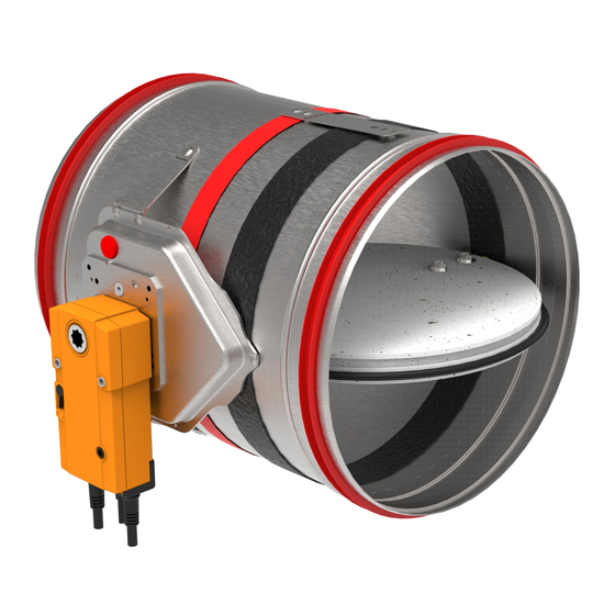
All fire dampers Fire dampers FDC25 are produced up to size d315 and have 25 mm thick damper blade. are tested according to the EN 1751 for airtightness and retain class 2 leakage on the Fire dampers FDC40 are produced in sizes from d355 till d800 and have 40 mm thick closed damper blade and class C on the casing air leakage. - Page 4 Galvanized steel casing Gypsum layers Fire resistant damper blade Intumescent strip Actuator Cold smoke seal Intumescent joint Contact layer Connection flanges Thermal fuse SOLID AIR ® CLIMATE SOLUTIONS • T +31 598 36 12 21 • www.solid-air.com • mail@solid-air.com - 58...
- Page 5 Declaration of Performance. Walls or ceilings with greater fire resistance can also be used. Fire damper should be installed according to the installation manual which can be found within this document. SOLID AIR ® CLIMATE SOLUTIONS • T +31 598 36 12 21 •...
-
Page 6: Technical Data
EN 13501-3, EN 1366-2, EN 15650, EN 1751, 7. Classification according to EN 13501-3 CPR no. 305/2011 (see page 5) Declaration of performance DoP 711/2020_12_EN SOLID AIR ® CLIMATE SOLUTIONS • T +31 598 36 12 21 • www.solid-air.com •... - Page 7 > > 15,69 13,91 0,428 0,389 0,344 0,325 0,312 0,232 0,206 0,179 FDC40 19,39 17,41 30,86 28,36 39,24 36,42 49,86 46,68 SOLID AIR ® CLIMATE SOLUTIONS • T +31 598 36 12 21 • www.solid-air.com • mail@solid-air.com - 58...
-
Page 8: Models
FDC25-APP Cylindrical fire damper with integrated Applique installation frame with 25 mm damper blade and fire classification up to EI90S. Sizes range from d100 till d315. SOLID AIR ® CLIMATE SOLUTIONS • T +31 598 36 12 21 • www.solid-air.com •... -
Page 9: Ordering Key
- electric actuator AC/DC 24V with connection plug FDC40-MF2 - 355 to 800 EMS-S - electromagnetic drive - ATEX rated Schischek 230/24V electric actuator SOLID AIR ® CLIMATE SOLUTIONS • T +31 598 36 12 21 • www.solid-air.com • mail@solid-air.com... - Page 10 Standard thermoelectric release point is 72 °C, optional 95 °C. SOLID AIR ® CLIMATE SOLUTIONS • T +31 598 36 12 21 •...
-
Page 11: Dimensions
Ød/2+22 • Optional with end position switches (-R-S). • FDC25 fire dampers are equipped with R25 manual mechanism. • FDC40 fire dampers are equipped with R40 manual mechanism. Length of damper blade outside of casing (Y dimension on front side) FDC 40 (>... - Page 12 Length of damper blade outside of casing (Y dimension on front side) FDC 40 (> d540) X = (Ø d/2)-270 (mm) (X is not visible in the drawing) FDC 25/40 Y = (Ø d/2)-110 (mm) SOLID AIR ® CLIMATE SOLUTIONS • T +31 598 36 12 21 • www.solid-air.com •...
- Page 13 Actuators >> Models >> Accessories >> Ordering key >> Replacements >> Dimensions >> Maintenance and operation FDC25/FDC40-M FDC25/FDC40-M (up to d315) Ød /2+12 Ød /2+12 DIMENSIONS Product (mm) (mm) (mm) (mm) BFL (M) BFN (M) BF (M) FDC25-M FDC40-M Ø d (mm)
- Page 14 • Made out of calcium silicate boards. • Quick wall mounting with screws. FDC25-APP-M • Factory assembled to the fire damper. 100 45 SOLID AIR ® CLIMATE SOLUTIONS • T +31 598 36 12 21 • www.solid-air.com •...
- Page 15 • Quick wall mounting with screws. • Factory assembled to the fire damper. FDC25-MF1-M Ød +118 Dn+118 D n + 1 1 8 3 8 0 SOLID AIR ® CLIMATE SOLUTIONS • T +31 598 36 12 21 • www.solid-air.com • mail@solid-air.com...
- Page 16 • Made out of calcium silicate boards. • Quick wall mounting with screws. • Factory assembled to the fire damper. FDC25-MF2-M Ød +118 103,5 SOLID AIR ® CLIMATE SOLUTIONS • T +31 598 36 12 21 • www.solid-air.com • mail@solid-air.com...
- Page 17 Ød +120 • Made out of calcium silicate boards. 103,5 • Quick wall mounting with screws. • Factory assembled to the fire damper. SOLID AIR ® CLIMATE SOLUTIONS • T +31 598 36 12 21 • www.solid-air.com • mail@solid-air.com...
-
Page 18: Installations
Ø d > 450 Ø d + 55 mm The FDC25 / FDC40 fire damper is always tested in standardized support frames (both in a rigid wall and in a flexible wall) in accordance with EN 1366-2: 2015 table 3/4/5. The... - Page 19 Plasterboard type A (EN520) Applique (installation frame) EI 90 (ve i↔o)S 500 Pa Gypsum plaster, mortar sealing or mortar and FDC25:EI 60 (ve i↔o)S Aerated concrete ( ≥ 550 kg/m MF1 (installation frame) cover boards. Rigid wall ≥ 100 mm 500 Pa Reinforced concrete (≥...
- Page 20 *Multiple fire dampers can be installed next to each other or ceiling/wall with the minimal distance of 30 mm between them. See page Test the operation of the damper blade! SOLID AIR ® CLIMATE SOLUTIONS • T +31 598 36 12 21 •...
- Page 21 *Multiple fire dampers can be installed next to each other or ceiling/wall with the mini- mal distance of 30 mm between them. See page Test the operation of the damper blade! SOLID AIR ® CLIMATE SOLUTIONS • T +31 598 36 12 21 •...
- Page 22 *Multiple fire dampers can be installed next to each other or ceiling/wall with the minimal distance of 30 mm between them. See page Test the operation of the damper blade! SOLID AIR ® CLIMATE SOLUTIONS • T +31 598 36 12 21 •...
- Page 23 *Multiple fire dampers can be installed next to each other or ceiling/wall with the mini- mal distance of 30 mm between them. See page Test the operation of the damper blade! SOLID AIR ® CLIMATE SOLUTIONS • T +31 598 36 12 21 •...
- Page 24 4. *Multiple fire dampers can be installed next to each other or ceiling/wall with the minimal distance of 30 mm between them. See page Test the operation of the damper blade! SOLID AIR ® CLIMATE SOLUTIONS • T +31 598 36 12 21 •...
- Page 25 *Multiple fire dampers can be installed next to each other or ceiling/wall with the minimal distance of 30 mm between them. See page Test the operation of the damper blade! SOLID AIR ® CLIMATE SOLUTIONS • T +31 598 36 12 21 •...
- Page 26 *Multiple fire dampers can be installed next to each other or ceiling/wall with the minimal distance of 30 mm between them. See page Test the operation of the damper blade! SOLID AIR ® CLIMATE SOLUTIONS • T +31 598 36 12 21 •...
- Page 27 3. /3*. Fill the space between the damper and the slab with mortar (2) or gypsum plaster. Test the operation of the damper blade! Installatie in de vloer Installatie in het plafond SOLID AIR ® CLIMATE SOLUTIONS • T +31 598 36 12 21 •...
- Page 28 Installation in the floor Installation in the ceiling check page 29 rigid floor/page 30 ceiling of this manual. Test the operation of the damper blade! SOLID AIR ® CLIMATE SOLUTIONS • T +31 598 36 12 21 • www.solid-air.com • mail@solid-air.com - 58...
- Page 29 4. To finish the installation please follow the steps (2 - 4) from this page. min. 100 Test the operation of the damper blade! SOLID AIR ® CLIMATE SOLUTIONS • T +31 598 36 12 21 • www.solid-air.com •...
- Page 30 4. To finish the installation please follow the steps (2 - 4) from this page. Test the operation of the damper blade! SOLID AIR ® CLIMATE SOLUTIONS • T +31 598 36 12 21 •...
- Page 31 2. Insert fire damper into wall and fasten with screws (8 pcs, 4.8 x 60 mm). 200-315 Ø d + 80 mm Ø d + 90 mm Test the operation of the damper blade! SOLID AIR ® CLIMATE SOLUTIONS • T +31 598 36 12 21 • www.solid-air.com •...
- Page 32 Test the operation of the damper blade! 125-180 Ø d + 95 mm Ø d + 105 mm 200-315 Ø d + 80 mm Ø d + 90 mm SOLID AIR ® CLIMATE SOLUTIONS • T +31 598 36 12 21 • www.solid-air.com • mail@solid-air.com...
- Page 33 Ø d + 80 mm Ø d + 90 mm 2. Fasten the fire damper with screws (8 pcs, 4.8 x 60 mm). Test the operation of the damper blade! SOLID AIR ® CLIMATE SOLUTIONS • T +31 598 36 12 21 •...
- Page 34 > > INSTALLATION 1. Create an opening in the wall (FDC25- Ø d +10 mm, FDC40-Ø d + 25 mm). Damper blade must be closed during installation! 2. Place the damper in the opening. 3. Fasten the fire damper with screws.
- Page 35 > > INSTALLATION 1. Create an opening in the wall (FDC25- Ø d +10 mm, FDC40-Ø d + 25 mm). Damper blade must be closed during installation! 2. Place the damper in the opening. 3. Fasten the fire damper with screws.
- Page 36 > > INSTALLATION 1. Create an opening in the wall (FDC25 - Ø d + 10 mm, FDC40 - Ø d + 25 mm) and build the subframe according to the drawing, see page Damper blade must be closed during installation! 2.
- Page 37 2. Place the fire damper in the opening. 3. Insert fire damper into wall and fasten with screws (12 pcs 6 x 160 mm). FDC25 FDC25: 4 pcs 6 x 160 mm FDC40: 12 pcs 6 x 160 mm Ø(d+G) FDC40...
- Page 38 On connection wool-wall apply glue Isover BSK in thickness of 2 mm. Repeat the same procedure on the other side. Place the wool on ventilation duct in length of 80 mm. SOLID AIR ® CLIMATE SOLUTIONS • T +31 598 36 12 21 •...
- Page 39 2. Insert the fire dampers into the wall and fill the space between the casings with mine- ral wool (140 kg/m³) up to flanges. Fill the space between the wall/ceiling with mineral wool (140 kg/m³) up to flanges. SOLID AIR ® CLIMATE SOLUTIONS • T +31 598 36 12 21 •...
- Page 40 >> Technical data >> Actuators >> Models >> Accessories >> Ordering key >> Replacements >> Dimensions >> Maintenance and operation > > SOLID AIR ® CLIMATE SOLUTIONS • T +31 598 36 12 21 • www.solid-air.com • mail@solid-air.com - 58...
- Page 41 Subframe should be prepared according to the drawings below. > > FDC25 FDC40 FDC25-MF1 FDC40-MF2 (d+80)/2 (d+25)/2 (d+10) (d+80) (d+25) (d+80) SOLID AIR ® CLIMATE SOLUTIONS • T +31 598 36 12 21 • www.solid-air.com • mail@solid-air.com - 58...
-
Page 42: Actuators
> ACTUATORS R25 manual actuator is installed on FDC25 fire dampers up to size d315. It is available in version with (R-S) and without (R) end switches. End switches and thermal fuse are easily replaceable and available as service parts. To upgrade to EMS change R25 to R40. - Page 43 Electromagnet is constantly under power and activates closing of the damper blade in case the power cuts out. Upon closure, damper blade is locked in closed position and can only be opened manually. Thermal fuse melting point is 72 °C. EMS-S mechanism is the same for FDC25/FDC40 fire dampers. MAGM NF NO...
- Page 44 Belimo BFL and BFN. After release, damper will be closed by return (ambient temperature) max. 72 °C. spring. When damper is opened manually, electric actuator will not move the damper into closed position in case of power failure. SOLID AIR ® CLIMATE SOLUTIONS • T +31 598 36 12 21 •...
- Page 45 II of the directive 94/9/EC. SOLID AIR ® CLIMATE SOLUTIONS • T +31 598 36 12 21 •...
-
Page 46: Accessories
CSP - GKF board set (for either side of the installation) Nominal diameter of the cylindrical fire damper FLEX - Flexible channel connection (1 pcs) SG - Safety grilles (1 pcs) SOLID AIR ® CLIMATE SOLUTIONS • T +31 598 36 12 21 •... - Page 47 Upgrade R25 to electric actuator Ombouw kit B Upgrade R40 to electric actuator R40 handmatig mechaniek FD-A-R40 (see page Rooksensor page 48 SOLID AIR ® CLIMATE SOLUTIONS • T +31 598 36 12 21 • www.solid-air.com • mail@solid-air.com - 58...
- Page 48 Green - service alarm (contamination) LED on smoke detector Red - smoke alarm Green - normaal bedrijf LED on PCB Yellow - system error Yellow - Low-Flow SOLID AIR ® CLIMATE SOLUTIONS • T +31 598 36 12 21 • www.solid-air.com • mail@solid-air.com...
- Page 49 Test/Reset* Technical documentation Calectro Test/Reset* Test/Reset* 24V AC/DC 230V AC/DC 24V AC/DC 230V AC/DC 24V AC/DC 230V AC/DC 24V AC/DC 230V AC/DC SOLID AIR ® CLIMATE SOLUTIONS • T +31 598 36 12 21 • www.solid-air.com • mail@solid-air.com - 58...
- Page 50 3. Rotate smoke sensor (0° - 180°) according to air flow directiona and fix it with screws. 4. Put the casing back and instal the cover. Pay attention to detail A! AIRFLOW DIRECTION SOLID AIR ® CLIMATE SOLUTIONS • T +31 598 36 12 21 •...
-
Page 51: Replacements
Screw the board to the plate. Put the cover back in place. > > UPGRADE TO END CONTACTS (R40 R40-S) Video instructions https://www.youtube.com/watch?v=NCs5Y_3OagY&feature=you tu.be&ab_channel=Klimaopremad.d. SOLID AIR ® CLIMATE SOLUTIONS • T +31 598 36 12 21 • www.solid-air.com • mail@solid-air.com - 58... - Page 52 CEDC board. > > 4. Put the cover back in place. Video instruction https://www.youtube.com/watch?v=F4zu5FyEGRUa Test the operation of the damper blade! SOLID AIR ® CLIMATE SOLUTIONS • T +31 598 36 12 21 • www.solid-air.com • mail@solid-air.com - 58...
- Page 53 3. Remove the old thermal fuse. Insert a new thermal fuse and screw it back on. 4. Put the cover back in place. > > Video instruction Test the operation of the damper blade! https://www.youtube.com/watch?v=1DgrF_K5_a8 SOLID AIR ® CLIMATE SOLUTIONS • T +31 598 36 12 21 • www.solid-air.com • mail@solid-air.com...
- Page 54 Put the CEDC board and the cover back in place. > > Test the operation of the damper blade! Video instruction https://www.youtube.com/watch?v=5sHKuD9boCI SOLID AIR ® CLIMATE SOLUTIONS • T +31 598 36 12 21 • www.solid-air.com •...
- Page 55 NOTE: Install the thermal fuse in a place where it will not interfere with the operation of > > the damper blade! Video instruction https://www.youtube.com/watch?v=t54DTocVKDs&feature=youtu.be Test the operation of the damper blade! SOLID AIR ® CLIMATE SOLUTIONS • T +31 598 36 12 21 • www.solid-air.com • mail@solid-air.com...
- Page 56 NOTE: Install the thermal fuse in a place where it will not interfere with the operation of > > the damper blade! Video instruction Test the operation of the damper blade! https://www.youtube.com/watch?v=t54DTocVKDs&feature=youtu.be SOLID AIR ® CLIMATE SOLUTIONS • T +31 598 36 12 21 • www.solid-air.com • mail@solid-air.com...
- Page 57 4. Fix the transition plate to the transition board and put the Belimo actuator back. > > Test the operation of the damper blade! Video instruction https://www.youtube.com/watch?v=t54DTocVKDs&feature=youtu.be SOLID AIR ® CLIMATE SOLUTIONS • T +31 598 36 12 21 • www.solid-air.com •...
-
Page 58: Maintenance And Operation
By a button - the damper blade must be closed by pressing the button. • Check the if the electrical terminals are tightened. SOLID AIR ® CLIMATE SOLUTIONS • T +31 598 36 12 21 •...
Need help?
Do you have a question about the FDC25 and is the answer not in the manual?
Questions and answers