Table of Contents
Advertisement
Quick Links
DESCRIPTION
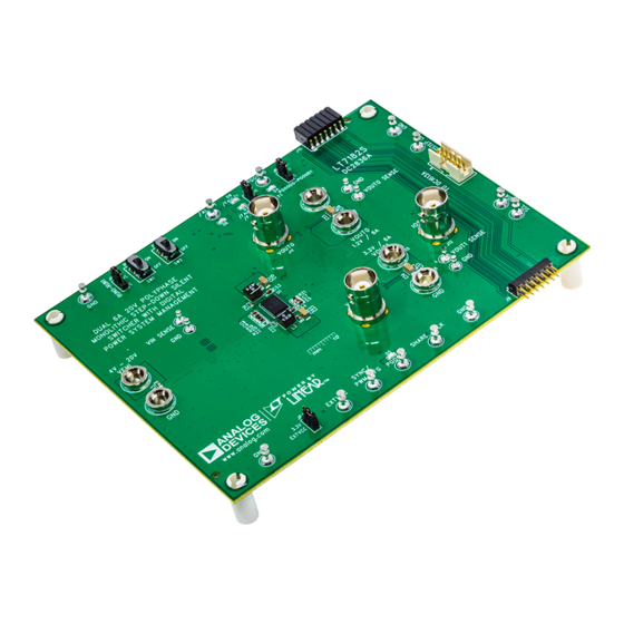
Demonstration Circuit 2836A is a dual-output PolyPhase
DC/DC synchronous step-down regulator with 4V to 20V
input range featuring
LT
ply 6A continuous/9A maximum transient load current.
LT7182S is a dual 6A monolithic step-down regulator.
The second-generation Silent Switcher
incorporated into LT7182S to minimize EMI and reduce
PCB layout sensitivity. It also integrates digital power sys-
tem management function allowing for programmability
and telemetry with a PMBus/I
face. Please see LT7182S data sheet for more detailed
information.
The demonstration circuit 2836A runs at 1MHz to mini-
mize solution size. The peak efficiency at 12V input is
83.2% for 1.2V rail and 91.1% for 3.3V rail. The IC tem-
perature rise is 70°C when both channels run at full load,
6A each, at 1MHz.
The demo board has EMI filters installed for both chan-
nels. The conducted and radiated EMI performances of
the board (with EMI filters) are shown in Figure 2. The red
lines in Figure 2 are CISPR25 CLASS 5 limit.
PERFORMANCE SUMMARY
SYMBOL
PARAMETER
V
Input Voltage Range
IN
V
Output0 Voltage
OUT0
I
Maximum Output0 Current
OUT0
V
Output1 Voltage
OUT1
I
Maximum Output1 Current
OUT1
f
Switching Frequency
SW
EFE
Efficiency at DC
Dual Channel 6A, 20V, PolyPhase
Step-Down Silent Switcher with Digital
7182S. Each output can sup-
®
structure is
®
2
C compliant serial inter-
Specifications are at T
CONDITIONS
V
IN
V
IN
DEMO MANUAL DC2836A
Power System Management
DC2836A powers up to default settings and produces
®
power based on configuration resistors without the need
for any serial bus communication. This allows easy evalu-
ation of the DC/DC converter. To fully explore the power
system management features of the part, download the
GUI software LTpowerPlay
2
I
C/SMBus/PMBus dongle DC1613A to connect to the
board. LTpowerPlay allows the user to reconfigure the part
on the fly and store the configuration in EEPROM, view
telemetry of voltage, current, temperature and fault status.
GUI Download
The software can be downloaded from:
The LT7182S data sheet gives a complete description of
the part, operation and application information. The data
sheet must be read in conjunction with this demo manual
for DC2836A.
For more details and instructions of LTpowerPlay, please
refer to LTpowerPlay GUI for LT7182S Quick Start Guide.
Design files for this circuit board are
All registered trademarks and trademarks are the property of their respective owners.
= 25°C
A
= 12V, I
= 3A, I
= 0A
OUT0
OUT1
= 12V, I
= 3A, I
= 0A
OUT1
OUT0
LT7182S
onto your PC and use ADI's
®
LTpowerPlay
available.
MIN
TYP
MAX
4
20
1.2
9
3.3
9
0.925
1
1.075
83.2
91.1
UNITS
V
V
A
V
A
MHz
%
%
Rev. 0
1
Advertisement
Table of Contents

Related Manuals for Analog Devices LT7182S


Summary of Contents for Analog Devices LT7182S
- Page 1 EEPROM, view and telemetry with a PMBus/I C compliant serial inter- telemetry of voltage, current, temperature and fault status. face. Please see LT7182S data sheet for more detailed GUI Download information. The software can be downloaded from:...
- Page 2 8. Connect the dongle and control the output voltages NOTE: Make sure that the input voltage never exceeds 20V. from the GUI. See LTpowerPlay GUI for the LT7182S Quick Start Guide for details. 4. Check for the proper output voltages of 1.2V ±0.5% (1.194V ~ 1.206V) and 3.3V ±0.5% (3.283V ~ 3.317V).
-
Page 3: Quick Start Procedure
DEMO MANUAL DC2836A QUICK START PROCEDURE Conducted EMI Performance (CISPR25 Conducted Emission Test with Class 5 Peak Limits) CLASS 5 PEAK LIMIT –10 CONDUCTED PEAK MAX –20 100k FREQUENCY (kHz) dc2836a F02a DC2836A DEMO BOARD (WITH EMI FILTER INSTALLED) 14V INPUT TO 1.2V OUTPUT0 PLUS 3.3V OUTPUT1 AT 6A = 1MHz Radiated EMI Performance (CISPR25 Radiated Emission Test with Class 5 Peak Limits) - Page 4 DEMO MANUAL DC2836A QUICK START PROCEDURE Figure 3. Proper Measurement Equipment Setup Rev. 0...
-
Page 5: Input Power Supply
You can use a PC to reconfigure the power manage- GPIOs and other functionalities. The DC1613A dongle ment features of the LT7182S such as: nominal V may be plugged when V is present. - Page 6 (with no hardware present) in order to build a software can be downloaded from: multichip configuration file that can be saved and reloaded LTpowerPlay | Analog Devices at a later time. LTpowerPlay provides unprecedented diag- To access technical support documents for LTC Digital nostic and debug features.
- Page 7 In the Toolbar, click the R (RAM to PC) icon to read the RAM from the LT7182S. This reads the configu- ration from the RAM of LT7182S and loads it into f. Save the demo board configuration to a (*.proj) file.
- Page 8 RES., 107k, 1%, 1/10W, 0603 VISHAY, CRCW0603107KFKEA RES., 80.6k, 1%, 1/10W, 0603 VISHAY, CRCW060380K6FKEA IC, REGULATOR, LQFN-40 ANALOG DEVICES, LT7182SRV#PBF Additional Demo Board Circuit Components CAP ., 1µF, X5R, 50V, 10%, 0603 MURATA, GRM188R61H105KAALD CAP ., 0.01µF, X7R, 25V, 10%, 0603 TDK, C1608X7R1E103K080AA CAP ., 100µF, ALUM, 35V...
-
Page 9: Parts List
RES., OPTION, 2010 RES., 0.01Ω, 1%, 1W, 2512 VISHAY, WSL2512R0100FEA IC, EEPROM, 2Kb (256x8), TSSOP-8 MICROCHIP , 24LC025-I/ST IC, IDEAL DIO, 10DFN ANALOG DEVICES, LTC4413EDD#PBF IC, LDO, TSOT23-5 ANALOG DEVICES, LT1761ES5-3.3#PBF Hardware: For Demo Board Only E1, E2, J3-J6 BANANA JACK, FEMALE... - Page 10 DEMO MANUAL DC2836A SCHEMATIC DIAGRAM Rev. 0...
-
Page 11: Schematic Diagram
Devices for its use, nor for any infringements of patents or other rights of third parties that may result from its use. Specifications subject to change without notice. No license is granted by implication or otherwise under any patent or patent rights of Analog Devices. - Page 12 Board until you have read and agreed to the Agreement. Your use of the Evaluation Board shall signify your acceptance of the Agreement. This Agreement is made by and between you (“Customer”) and Analog Devices, Inc. (“ADI”), with its principal place of business at One Technology Way, Norwood, MA 02062, USA. Subject to the terms and conditions of the Agreement, ADI hereby grants to Customer a free, limited, personal, temporary, non-exclusive, non-sublicensable, non-transferable license to use the Evaluation Board FOR EVALUATION PURPOSES ONLY.
- Page 13 Mouser Electronics Authorized Distributor Click to View Pricing, Inventory, Delivery & Lifecycle Information: Analog Devices Inc. DC2836A...
Need help?
Do you have a question about the LT7182S and is the answer not in the manual?
Questions and answers