
Related Manuals for Faria Serial Bus


Summary of Contents for Faria Serial Bus
- Page 1 Serial Bus for CorrectCraft ® Pleasurecraft GM Engines Visual /Audible Alert Messages Easy Installation Waterproof Connections Easy to Read Digital Displays Easy to use Depth Sounder Multiple Interfaces IS0151 ISO151C ECR#4418 03/08/2004...
- Page 2 Initial Setup Selecting the Fuel Tank Size Page 2 Operation General Page 2 Speedometer/Depth Sounder Speedometer Calibration Page 3 Dual Pitot Operation Page 4 Depth Sounder Page 4 Canceling Depth Alarms Page 4 Shallow Alarm Page 5 Deep Alarm Page 5 Keel Offset Page 6 Units...
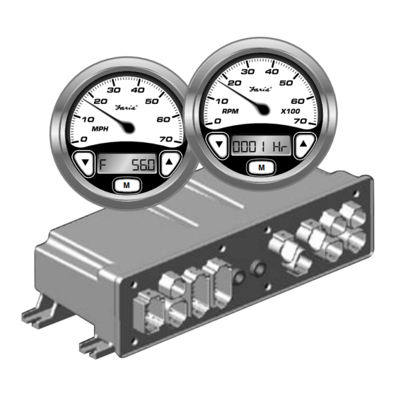
- Page 3 Operation • optional second 5” Speedometer • Various 2” instruments, including General but not limited to The Faria® Serial Bus™ system is designed to receive information from the • Voltmeter engine ECU and various individual • Oil Pressure gauge sensors throughout the boat. This •...
- Page 4 Speedometer / Depth Sounder measured by the GPS or radar. Adjust the speedometer pointer by pressing the “Up” The Serial Bus Speedometer / Depth or “Down” buttons until the speedometer Sounder provides both the functions of a matches the GPS or radar speed.
- Page 5 Depth Sounder The speedometer also measures the water pressure in the pitot tubes when power is The depth sounder is turned on and off first turned on. This measurement is with the ignition switch. The depth subtracted from later readings to correct sounder can also be turned off at any time, for the pressure caused by the weight of while in depth display mode, by pressing...
- Page 6 The display will show “S X.X” Down Button Button alarm will resume if the condition that caused the alarm is not corrected. The which is the current setting for the shallow operator can cancel the alarm as many alarm. Pressing the “Up” or “Down” times as necessary, until the condition is buttons will change the shallow setting.
- Page 7 Holding the “mode M” button in for 2 seconds will save the new deep setting and change the display back to the normal depth mode. Set to zero to disable alarm. Down Button Button Mode buttons will cycle through the choices. Button Pressing and holding the “mode M”...
- Page 8 Speedometer Display Sequence Quick Quick Press Press Pitot Status Air Temperature Hold (optional) Adjust Save Quick Press Water Temperature No Save (optional) Quick Press Depth Sounder Hold Shallow Alarm Set Deep Alarm Set Keel Offset Select Units Figure 1 Page 7...
- Page 9 Tachometer / Fuel Monitor RPM limit Knock sensing system malfunction The Serial Bus Tachometer / Fuel Monitor Ignition system malfunction instrument provides both the functions of a Manifold pressure sensor (MAP) tachometer and a fuel - engine monitoring malfunction system. The analog tachometer is a stepper...
- Page 10 Hours Remaining Instrument Lights The “time remaining” display shows how The navigation light switch must be on for many hours the boat can operate based on the instrument lights to function. The “Up” the fuel remaining in the tank and the and “Down”...
- Page 11 Tachometer Display Sequence Quick Quick Press Press Hourmeter Voltmeter Quick Quick Press Press Hours Remaining Oil Pressure Quick Press Engine Temperature Figure 2 LCD Alarm Condition Displays. messages, simultaneously press both the Alarm messages will be displayed on the “Up” and “Down” buttons on the Tachometer LCD display.
- Page 12 Severe Conditions- Includes a Flashing Red Light Low Battery Voltage (Flashing Red Light) High Engine Temperature (Flashing Red Light) Low Oil Pressure (Flashing Red Light) Low Fuel Level (Flashing Red Light) RPM Reduction in Progress (Flashing Red Light) Warnings Engine Speed Limiter Active Knock Detection System Malfunction Spark Delivery System Malfunction Manifold Pressure System Malfunction...
- Page 13 This page left blank intentionally.
- Page 14 The Faria Serial Bus Pilot and the Faria Speedometer-PerfectPass Cruise instruments are “end of the bus” instruments. Only the provided four (4) pin connector is to be connected to the “Faria Bus” . See special instructions for use of the six (6) pin connector on these instruments.
- Page 15 Faria Serial Bus Gateway Typical Power Connections Black To Air and Water Temp. Sender Grounds Black Purple Figure 3 Battery Typical Instrument Connections PJ0018 Note: To help reduce moisture in the gauges be sure to install plug PJ0018 in all open connectors.
- Page 16 Faria Serial Bus Gateway Pleasurecraft GM Engine ECU Connection Shield Shield (Not Connected) MEFI IV Black (Data Ground) Black Engine ECU White White (Data) Figure 5 Transducer and Pitot Tubes Connections Blue Blue Black Black(shield) Airmar Depth Sounder Black (shield)
- Page 17 Faria Serial Bus Gateway Miscellaneous Connections Figure 7 Dk. Blue Nav. Lt. Blue White White Pink Light Switch Instrument Water Fuel Backlight Pressure Temp. Surface Tank Control Sender Sender Sender Temp. Sender Brown (Bare) Brown Page 16...
- Page 18 Not used Battery Positive (always on)* Ground (Temp. Sender) Black Switched Power from Ignition Purple switch circuit Ground Black Faria® Bus Data and Instrument Power Not Used (PJ0015) Not Used (PJ0016) MEFI IV Engine ECU Not Used Starboard Pitot Not Used...
- Page 19 Notes...
- Page 20 Copyright 2004 by the Thomas G. Faria Corporation, Uncasville, CT USA No part of this publication may by reproduced in any form, in an electronic retrieval system or otherwise, without the prior written permission of the company. Faria® is the trademark of the Thomas G. Faria Corporation...
Need help?
Do you have a question about the Serial Bus and is the answer not in the manual?
Questions and answers