Table of Contents
Advertisement
All manuals and user guides at all-guides.com
Pilot
Owner's Manual
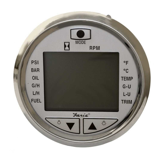
Pilot I Displays,
Speedometer in MPH and Knots
Trip Log
Clock
Voltmeter
Air & Surface Temp.
Digital Depth Sounder
with Deep and Shallow water alarms,
Keel offset
Audible and Visual Alarms
T
1
MODE
S
D
KL
I
™
T
1
F
M
FA
DIS
MPH
KTS
IS0152
ISO152B ECR#3704 6/2003
Advertisement
Table of Contents

Related Manuals for Faria Pilot 1


Summary of Contents for Faria Pilot 1
- Page 1 All manuals and user guides at all-guides.com MODE Pilot ™ Owner’s Manual Pilot I Displays, Speedometer in MPH and Knots Trip Log Clock Voltmeter Air & Surface Temp. Digital Depth Sounder with Deep and Shallow water alarms, Keel offset Audible and Visual Alarms IS0152 ISO152B ECR#3704 6/2003...
-
Page 2: Table Of Contents
All manuals and user guides at all-guides.com Description Key Pad Functions Page 1 Installation 4 pin Connector Page 2 6 pin Connector Page 2 Operations General Modes Power On Page 3 Illumination Page 3 Normal Mode Page 3 Select Mode Activating Page 3 Selecting upper or lower display... -
Page 3: Key Pad Functions
Illumination Off Illumination On Faria Pilot I Description The Faria Pilot I system is a multifunctional instrument designed to give two simultaneous readouts of several different and independent functions on an upper and lower LCD display. A digital Bar Graph provides continuous display of the battery system voltage. -
Page 4: Pin Connector
All manuals and user guides at all-guides.com Used for all splices. Wires 6-Pin Male Connector Note: For wiring 6-Pin Female diagram for the Connector 6 - Pin connector see Heat Shrink Tube (red or blue) Yamaha (HN0362) Metal Butt Connector (red or blue). -
Page 5: Power
All manuals and user guides at all-guides.com Normal Mode: Operation: Pilot is operating showing the last selected Power ON: Functions. The Pilot I instrument will turn on when NOTE: When in either the Select or the ignition key switch is set to the run Edit Modes if no button is pushed for 5 position. -
Page 6: Selecting Display Function
All manuals and user guides at all-guides.com Selecting upper or lower active display: Activate the Select Mode and while the display is flashing, press the “Up” arrow selected active display and the Pilot will beep each time the “MODE” button is pressed. -
Page 7: Upper Display Functions
All manuals and user guides at all-guides.com If no buttons are pushed within 5 seconds, Continue pressing the “MODE” button the Pilot will revert automatically to the again until the Function Indicator is Normal Mode. pointing to FT, M or FA. (The Function Indicator will automatically You can also enter the Edit Mode while in point to the last unit type selected. -
Page 8: Setting Shallow Alarm
All manuals and user guides at all-guides.com will flash on the LCD next to the “S” and Setting the Deep Alarm: the audible alarm will sound rapidly. Press and hold the “MODE” button until When the deep depth setting is read by the the Pilot beeps to select the Edit Mode. -
Page 9: Loss Of Signal
All manuals and user guides at all-guides.com Press and hold the “MODE” button until If the upper display depth sounder the Pilot beeps to select the Edit Mode. function is active the (SIG) will illuminate and hold. If any other upper display function is active the (SIG) will flash on and off alternately with the active function’s readout. -
Page 10: Resetting Timer
All manuals and user guides at all-guides.com Clock: Description: The clock will run continuously as long as power is applied to the Pilot. The clock reads hours and minutes. Continue pressing the “MODE” button Operation: Selecting the Clock Function. Press the “MODE” button and activate the Select Mode. -
Page 11: Setting The Clock
All manuals and user guides at all-guides.com reading to match a GPS or charted Setting the clock: distance run. Calibrating the distance Log Press and hold the “MODE” button until also automatically calibrates the Pilot beeps to select the Edit Mode. Speedometer. -
Page 12: Selecting Speedometer Units
All manuals and user guides at all-guides.com Selecting the Speedometer Units. Press and hold the “MODE” button until the Pilot beeps to select the Edit Mode. quickly until the lower display reads “C” Continue pressing the “MODE” button quickly until the lower display reads “Un” (units). -
Page 13: Selecting Distance Log Units
All manuals and user guides at all-guides.com Continue pressing the “MODE” button Calibrating the Distance Log: Press and hold the “MODE”button until again until the Function Indicator is the Pilot beeps to select the Edit Mode. Continue pressing the “MODE” button quickly until the lower display reads “c”... -
Page 14: Water And Air / Bait-Well Temperature
All manuals and user guides at all-guides.com Press either the “Up” or “Down” arrow button to clear the Log reading to zero. Water & Bait-well Selecting the Air / Water Temperature Temperature Units Description: Press and hold the “MODE” button until The Pilot I will monitor water surface the Pilot beeps to select Edit Mode. -
Page 15: Voltmeter
All manuals and user guides at all-guides.com Continue pressing the “MODE” button again until the display shows 00.0 and no other Lower Display Function Indicator is active except the one pointing to the Battery icon. Voltmeter: Description: The Voltmeter continuously monitors the battery system voltage supplied to the Pilot I. - Page 16 All manuals and user guides at all-guides.com Press the “MODE” button. The upper display changes to “bAtH” and the lower display shows the current high voltage warning setting. Bar Graph Display Press either the “Up” or “Down” arrow button to adjust the high voltage alarm setting.
- Page 17 All manuals and user guides at all-guides.com This page left blank intentionally. Page 15...
- Page 18 All manuals and user guides at all-guides.com Harness HN0362 To Pilot I 4 - pin connector Yamaha adaptor 4- pin connector (CN0082) Pin A +12 Battery Pin B Purple +12 Ignition Pin C Black Ground Pin D Blue Depth Sounder signal ECR 2065 2/12/02 Paddle Wheel triducer Shrink Tubing...
- Page 19 All manuals and user guides at all-guides.com Harness HN0362 To Pilot I 6 - pin connector Yamaha adaptor 2x PJ0005 Shrink Tubing or Wrap White/Blue Green Stripe (Paddle Wheel Signal) Air Temp.Sensor White White White Water Temp. Sensor signal Brown Green (Wt Temp Grnd) Black...
- Page 20 All manuals and user guides at all-guides.com Harness HN0365 To Pilot I 4 - pin connector 4- pin connector (CN0082) Pin A +12 Battery Pin B Purple +12 Ignition Pin C Black Depth Sounder (-) Pin D Blue Depth Sounder signal ECR 2152 03/07/02 Paddle Wheel triducer Shrink Tubing...
- Page 21 All manuals and user guides at all-guides.com Harness HN0365 To Pilot I 6 - pin connector 2x PJ0005 Shrink Tubing or Wrap White/Blue Stripe Green (Paddle Wheel Signal) Tan/White Air Temp.Sensor Tan/Blue Stripe White Stripe White Water Temp. Sensor signal Brown Black (Wt Temp Grnd) Black...
- Page 22 All manuals and user guides at all-guides.com NOTES...
- Page 23 All manuals and user guides at all-guides.com Copyright 2003 by the Thomas G. Faria Corporation, Uncasville CT No part of this publication may by reproduced in any form, in an electronic retrieval system or otherwise, without the prior written permission of the company.
Need help?
Do you have a question about the Pilot 1 and is the answer not in the manual?
Questions and answers