Table of Contents
Advertisement
Quick Links
Advertisement
Table of Contents

Subscribe to Our Youtube Channel
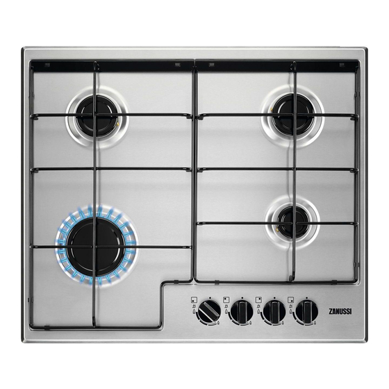
Summary of Contents for Zanussi ZGNN642X
- Page 1 User Manual GETTING STARTED? EASY. ZGNN642X EN User Manual...
-
Page 2: Safety Information
SAFETY INFORMATION Before the installation and use of the appliance, carefully read the supplied instructions. The manufacturer is not responsible for any injuries or damage that are the result of incorrect installation or usage. Always keep the instructions in a safe and accessible location for future reference. -
Page 3: Safety Instructions
CAUTION: The appliance must not be supplied through an • external switching device, such as a timer, or connected to a circuit that is regularly switched on and off by a utility. CAUTION: The cooking process has to be supervised. A short •... -
Page 4: Electrical Connection
• Keep the minimum distance from other • Connect the mains plug to the mains socket appliances and units. only at the end of the installation. Make sure that • Always take care when moving the appliance as there is access to the mains plug after the it is heavy. -
Page 5: Before The Installation
• This appliance is for cooking purposes only. It WARNING! Risk of fire and explosion must not be used for other purposes, for example room heating. • Do not let acid liquids, for example vinegar, • Fats and oil when heated can release flammable lemon juice or limescale remover, touch the hob. - Page 6 Model ........Make sure that, once the hob is installed, it is easily PNC ......... accessible for the engineer in the event of a Serial number ......breakdown. The manufacturer will not accept liability, should the IMPORTANT SAFETY REQUIREMENTS above instructions or any of the other safety This hob must be installed in accordance with the instructions incorporated in this instruction booklet Gas Safety (Installation and Use) Regulations...
-
Page 7: Injectors Replacement
Rigid connection: Carry out connection by using metal rigid pipes (copper with mechanical end). INJECTORS REPLACEMENT 1. Remove the pan supports. 2. Remove the caps and crowns of the burner. 3. With a socket spanner 7 remove the injectors and replace them with the ones which are necessary for the type of gas you use (see table in "Technical Data"... - Page 8 • Make sure that there is access to the mains plug C. Brown after the installation. D. Cord clamp Electrical Requirements E. Blue The wires in the cord are coloured as follows: Permanent electrical installation must agree with the latest I.E.E. Regulations and local Electricity Green and yellow - Earth Board regulations.
- Page 9 present. The cord clamp must be correctly If a furniture unit is installed at a attached to the outer sheath. distance of 400 mm above the hob, there must be a minimum ASSEMBLY safety distance of 50 mm to the left or right from the edge of the hob.
-
Page 10: Possibilities For Insertion
min 30 mm min 5 mm (max 150 mm) 60 mm A. Removable panel B. Space for connections CAUTION! Install the appliance only on a worktop with flat surface. Kitchen unit with oven The electrical connection of the hob and the oven POSSIBILITIES FOR INSERTION must be installed separately for safety reasons and The panel installed below the hob must be easy to... -
Page 11: Control Knob
CONTROL KNOB Symbol Description Symbol Description minimum gas supply no gas supply / off position ignition position / maximum gas supply DAILY USE 2. Keep the control knob pushed for equal or less WARNING! Refer to Safety chapters. than 10 seconds. This lets the thermocouple warm up. -
Page 12: Hints And Tips
TURNING THE BURNER OFF WARNING! Always turn the flame To put the flame out, turn the knob to the off down or switch it off before you position remove the pans from the burner. HINTS AND TIPS WARNING! Refer to Safety chapters. CAUTION! Make sure that the pots are placed centrally on the burner in order to get the maximum stability and... -
Page 13: Periodic Maintenance
CLEANING THE HOB Be very careful when you replace • Remove immediately: melted plastic, plastic the pan supports to prevent the foil, sugar and food with sugar, otherwise, the hob top from damage. dirt can cause damage to the hob. Take care to 2. -
Page 14: Labels Supplied With The Accessories Bag
Problem Possible cause Remedy The fuse is blown. Make sure that the fuse is the cause of the malfunction. If the fuse is blown again and again, contact a qualified electrician. Burner cap and crown are Place the burner cap and placed incorrectly. -
Page 15: Technical Data
TECHNICAL DATA HOB DIMENSIONS Width 594 mm Depth 510 mm BYPASS DIAMETERS BURNER Ø BYPASS 1/100 mm Rapid Semi-rapid Auxiliary OTHER TECHNICAL DATA Gas original: G20 (2H) 20 mbar 8 kW TOTAL POW- Gas replace- G30 (3+) 28-30 mbar 567 g/h ment: G31 (3+) 37 mbar 557 g/h... -
Page 16: Energy Efficiency
0,75 Semi-rapid 0,45 Auxiliary 0,33 ENERGY EFFICIENCY PRODUCT INFORMATION ACCORDING TO EU 66/2014 Model identification ZGNN642X Type of hob Built-in hob Number of gas burners Left rear - Semi-rapid 57.5% Right rear - Semi-rapid 57.5% Energy efficiency per gas burner... - Page 20 WWW.ZANUSSI.COM/SHOP...


Need help?
Do you have a question about the ZGNN642X and is the answer not in the manual?
Questions and answers