Table of Contents
Advertisement
Quick Links
USER'S MANUAL
Of
Intel Q87 Express Chipset
Based
M/B for LGA 1150 Quad Core Ready
Intel Core Processor
No. G03-NAF95-F
Rev: 1.0
Release date: July 25, 2013
Trademark:
* Specifications and Information contained in this documentation are furnished for information use only, and are
subject to change at any time without notice, and should not be construed as a commitment by manufacturer.
Advertisement
Table of Contents

Related Manuals for JETWAY NAF95-Q87


Summary of Contents for JETWAY NAF95-Q87
- Page 1 USER'S MANUAL Intel Q87 Express Chipset Based M/B for LGA 1150 Quad Core Ready Intel Core Processor No. G03-NAF95-F Rev: 1.0 Release date: July 25, 2013 Trademark: * Specifications and Information contained in this documentation are furnished for information use only, and are subject to change at any time without notice, and should not be construed as a commitment by manufacturer.
-
Page 2: Table Of Contents
TABLE OF CONTENT ENVIRONMENTAL SAFETY INSTRUCTION................iii ENVIRONMENTAL PROTECTION ANNOUCEMENT.............. iii USER’S NOTICE ........................iv MANUAL REVISION INFORMATION ..................iv ITEM CHECKLIST ........................iv CHAPTER 1 INTRODUCTION OF THE MOTHERBOARD SPECIFICATION ......................1 LAYOUT DIAGRAM....................2 CHAPTER 2 HARDWARE INSTALLATION JUMPER SETTING ..................... -
Page 3: Environmental Safety Instruction
Environmental Safety Instruction Avoid the dusty, humidity and temperature extremes. Do not place the product in any area where it may become wet. 0 to 40 centigrade is the suitable temperature. (The figure comes from the request of the main chipset) Generally speaking, dramatic changes in temperature may lead to contact malfunction and crackles due to constant thermal expansion and contraction from the welding spots’... -
Page 4: User's Notice
USER’S NOTICE COPYRIGHT OF THIS MANUAL BELONGS TO THE MANUFACTURER. NO PART OF THIS MANUAL, INCLUDING THE PRODUCTS AND SOFTWARE DESCRIBED IN IT MAY BE REPRODUCED, TRANSMITTED OR TRANSLATED INTO ANY LANGUAGE IN ANY FORM OR BY ANY MEANS WITHOUT WRITTEN PERMISSION OF THE MANUFACTURER. -
Page 5: Specification
Chapter 1 Introduction of the Motherboard 1-1 Specification Spec Description Design ATX form factor; PCB size: 30.5 x24.5 cm ® Intel Q87 Express Chipset Chipset ® ® Supports Intel Core™ i7, Core™ i5, Core™ i3 series, Pentium LGA1155 processor in LAG1150 Package CPU Socket * for detailed CPU support information please visit our website DDRIII RAM module slot x 4... -
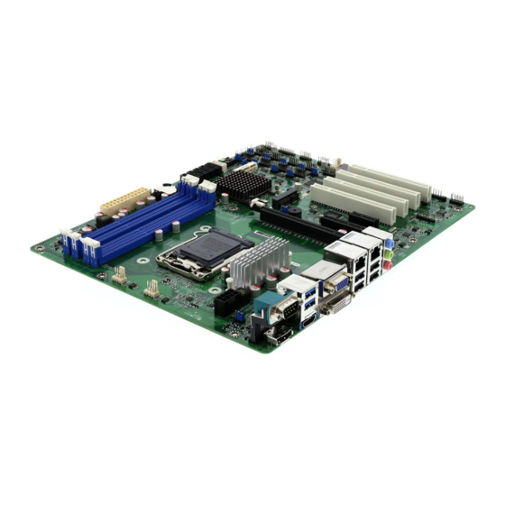
Page 6: Layout Diagram
1-2 Layout Diagram Rear IO Diagram RJ-45 LAN Ports Serial Port VGA Port USB 3.0 Ports Line-IN/ Optical SPDIF OUT Line-OUT MIC-IN HDMI Port DVI-D Port Display Port USB 2.0 Ports Motherboard Internal Diagram CPUFAN Header SYS FAN1 Header Serial Port over Display Port ATX 12V Power Connector... - Page 7 Motherboard Jumper Position JBAT JP14 CASE_OPEN JP13 JP11 JP12 JP10 Jumper Jumper Name Description COM1 Port Pin9 Function Select 4-pin Block COM2 Header Pin9 Function Select 4-pin Block COM3 Header Pin9 Function Select 4-pin Block COM5 Header Pin9 Function Select 4-pin Block COM7 Header Pin9 Function Select 4-pin Block...
- Page 8 Connectors Connector Name ATXPWR ATX Power Connector ATX12V ATX 12V Power Connector COM1 Serial Port COM Connector Display Port USB1 USB 3.0 Connector X2 HDMI High-Definition Multimedia Interface Video Graphic Attach Connector DVI1 DVI-D Port Connector UL1(Top)/UL2(Top) RJ-45 LAN Connector X2 UL1(Middle &...
-
Page 9: Hardware Installation
Chapter 2 Hardware Installation 2-1 Jumper Setting JP1 (4-pin): COM1 Port Pin9 Function Select JP1→COM1 Port 2 4 6 2 4 6 1 3 5 1 3 5 2-4 Closed: 3-4 Closed: 4-6 Closed: RI=RS232 RI= 5V; RI= 12V; JP9 (4-pin): COM2 Header Pin9 Function Select JP9→COM2 Header 2 4 6 2 4 6... - Page 10 JP6 (4-pin): COM5 Header Pin9 Function Select JP6→COM5 Header 2 4 6 2 4 6 1 3 5 1 3 5 2-4 Closed: 3-4 Closed: 4-6 Closed: RI=RS232 RI= 5V; RI= 12V; JP7 (4-pin): COM7 Header Pin9 Function Select JP7→COM7 Header 2 4 6 2 4 6 1 3 5...
- Page 11 JP10 (4-pin): COM4 Header Pin9 Function Select JP10→COM4 Header 2 4 6 2 4 6 1 3 5 1 3 5 2-4 Closed: 3-4 Closed: 4-6 Closed: RI=RS232 RI= 5V; RI= 12V; JP11 (4-pin): COM6 Header Pin9 Function Select JP11→COM6 Header 2 4 6 2 4 6 1 3 5...
- Page 12 JP13 (4-pin): COM10 Port Pin9 Function Select JP13→COM10 Header 2 4 6 2 4 6 1 3 5 1 3 5 2-4 Closed: 3-4 Closed: 4-6 Closed: RI=RS232 RI= 5V; RI= 12V; JP14 (2-pin): ME Features Select JP14 1-2 Open:ME Features Enabled; 1-2 Closed:ME Features Disabled.
- Page 13 JP2 (3-pin): Mini PCI-E (PE4) Slot VCC 3.3V/3.3 VSB Select JP2→PE4 Slot 1-2 Closed : MINI PCI-E VCC= 3.3V; 2-3 Closed : MINI PCI-E VCC= 3.3VSB JP4 (3-pin): MSATA Slot VCC 3.3V/3.3 VSB Select JP4→MSATA 1-2 Closed: MSATA VCC= 3.3V; 2-3 Closed: MSATA VCC= 3.3VSB CASE_ OPEN (2-pin): Case Open Message Display Function Select CASE_OPEN...
-
Page 14: Connectors And Headers
Connectors and Headers 2-2-1 Rear I/O Back Panel Connectors RJ-45 LAN Ports Serial Port VGA Port USB 3.0 Ports Line-IN/ Optical SPDIF OUT Line-OUT MIC-IN HDMI Port DVI-D Port Display Port USB 2.0 Ports (1) Serial port Connector: COM1 These two serial ports are for user to connect compatible mouse, modern or other peripherals. -
Page 15: Motherboard Internal Connectors
2-2-2 Motherboard Internal Connectors ATXPWR (24-pin block): Main Power Connector ATX Power Supply connector: This is a new defined 24-pins connector that usually comes with ATX case. The ATX Power Supply allows using soft power on momentary switch that connect from the front panel switch to 2-pins Power On jumper pole on the motherboard. - Page 16 (2) ATX12V (8-pin block): 12V Power Connector This is a new defined 8-pin connector that usually comes with ATX Power Supply that supports extra 12V voltage to maintain system power consumption. Without this connector might cause system unstable because the power supply can not provide sufficient current for system.
-
Page 17: Header Pin Definition
2-2-3 Header Pin Definition (1) FP_AUDIO (9-pin): Line-Out, MIC-In Header This header is connected to Front Panel Line-out, MIC connector with cable. FP_AUDIO Pin 1 Line-Out, MIC Header (2) CD_IN (4-pin): CD AUDIO-In Header CDIN header is for CD-Audio Input signal. Please connect it to CD-ROM CD-Audio output connector. - Page 18 (4) KBMS (6-pin): PS/2 Keyboard & Mouse Header Pin1 (5) GPIO_CON (10-pin): GPIO Header Pin 1 (6) CIR_CON (7-Pin): CIR Header Pin 1 CIR Header...
- Page 19 (7) TPM (19-pin): TPM Header Pin 1 (8) USB 3.0 Port Header (19-pin): USB2 Pin 1 (9) USB 2.0 Port Headers (9-pin): USB3/USB4 Pin 1...
- Page 20 (10) JW-FP (9-pin): Front Panel Header Pin 1 (11) JP15 (7-pin): PWR LED Header & Speaker Header Pin 1 (12) COM2/3/4/5/6/7/8/9/10 (9-Pin): Serial Port Header Pin6 Pin1 Pin5...
- Page 21 (13)SM_BUS (4-pin): SM BUS Header Pin 1 SM_BUS Header (14)NIC_LED1/ NIC_LED2 (2-pin): LANLED Header Pin1 LED+ LED- (15) SYSFAN1/SYSFAN2/CPUFAN1 (4-pin): FAN Headers Pin1 CPUFAN/SYSFAN1/SYSFAN2...
-
Page 22: Chapter 3 Introducing Bios
Chapter 3 Introducing BIOS Notice! The BIOS options in this manual are for reference only. Different configurations may lead to difference in BIOS screen and BIOS screens in manuals are usually the first BIOS version when the board is released and may be different from your purchased motherboard. Users are welcome to download the latest BIOS version form our official website. -
Page 23: Function Keys
Menu Bar General Help Items Current Setting Value Menu Items Function Keys BIOS Menu Screen Function Keys In the above BIOS Setup main menu of, you can see several options. We will explain these options step by step in the following pages of this chapter, but let us first see a short description of the function keys you may use here: Press←→... -
Page 24: Menu Bars
Press F1 to pop up a small help window that describes the appropriate keys to use and the possible selections for the highlighted item. To exit the Help Window, press <Esc>. 3-5 Menu Bars There are six menu bars on top of BIOS screen: Main To change system basic configuration Advanced... -
Page 25: Advanced Menu
3-7 Advanced Menu ERP Function Use this item to enable or disable ERP function for this board. This item should be set as [Disabled] if you wish to have Active All Wakeup Function. ► PCI Subsystem Settings Press [Enter] to enter and make settings for the following sub-items: PCI Common Settings: PCI Latency Timer Use this item to set value to be programmed into PCI latency timer register. - Page 26 BIOS to select the value. Maximum Read Request Use this item to set maximum read request size of PCI Express device or allow system BIOS to select the value. ► ACPI Settings Press [Enter] to make settings for the following sub-items: ACPI Settings ACPI Sleep State Use this item to select the highest ACPI sleep state the system will enter when the...
- Page 27 Execute Disable Bit The optional settings: [Disabled]; [Enabled]. Intel Virtualization Technology The optional settings: [Enabled]; [Disabled]. When set as [Enabled], a VHM can utilize the additional hardware capabilities provided by Vanderpool Technology. EIST Use this item to enable or disable Intel SpeedStep. Turbo Mode Use this item to enable or disable Turbo Mode.
- Page 28 Serial ATA Port 1/2/3/4/5/6/mSATA Port 1/ Port 2/ Port 3/ Port 4/ Port 5/ Port 6/ mSATA The optional settings: [Disabled]; [Enabled]. Use this item to enable or disable each SATA port. SATA Device Type The optional settings are: [Hard Disk Drive]; [Solid State Drive]. ►...
- Page 29 Amt Wait Timer Use this item to set time to wait before sending ASF_GET_BOOT_OPTIONS. Disable ME Use this item to set ME to soft Temporary Disabled function. Use this item to enable or disable Alert Specification Format. Active Remote Assistance Process Use this item to enable or disable Trigger CIRA boot function.
- Page 30 The optional settings are: [10 sec]; [20 sec]; [30 sec]; [40 sec]. Device power-up delay Use this item to set maximum time the device will take before it properly reports itself to the host controller. ‘Auto’ uses default value: for a root port it is 100 ms, for a hub port the delay is taken from hub descriptor.
- Page 31 ► Third Super IO Configuration ► COM7/COM8/COM9/COM10 Configuration Serial Port Use this item to enable or Disable serial port (COM). Change Settings Use this item to select an optimal setting for super IO device. ► WatchDog Configuration Press [Enter] to make settings for Watchdog Configuration: Watchdog Configuration: WatchDog Timer Control Use this item to enable or disable WatchDog Timer Control.
-
Page 32: Chipset Menu
3-8 Chipset Menu ► PCH-IO Configuration Press [Enter] to make settings for the following sub-items: ► USB Devices Configuration Press [Enter] to further setting USB device configuration. USB Configuration XHCI Mode Use this item to select mode of operation for XHCI controller. The optional settings are: [Smart Auto];... - Page 33 Onboard LAN2 Device Use this item to control the PCI Express root port. SLP_S4 Assertion Width Use this item to select a minimum assertion width of the SLP_S4# signal to ensure that the DRAMs has been safely power-cycled. The optional settings are: [1-2 Seconds]; [2-3 Seconds]; [3-4 Seconds]; [4-5 Seconds].
-
Page 34: Boot Menu
► PEG Configuration Press [Enter] to make settings for the following sub-items: PEG Slot Configuration PEG-Gen X The optional settings are: [Auto]; [Gen1]; [Gen2]; [Gen3]. Enable PEG The optional settings are: [Disabled]; [Enabled]; [Auto]. Detect Non-Compliance Device Use this item to detect non-compliance PCI Express device in PEG. The optional settings are: [Disabled];... -
Page 35: Security Menu
Boot Configuration Setup Prompt Timeout Use this item to set number of seconds to wait for setup activation key. Bootup Numlock State Use this item to select keyboard numlock state. The optional settings are: [On]; [Off]. Quiet Boot The optional settings are: [Disabled]; [Enabled]. Boot Option Priorities ►... -
Page 36: Save & Exit Menu
Security menu allow users to change administrator password and user password settings. 3-11 Save & Exit Menu Save Changes and Reset This item allows user to reset the system after saving the changes. Discard Changes and Reset This item allows user to reset the system without saving any changes. Restore Defaults Use this item to restore /load default values for all the setup options.
Need help?
Do you have a question about the NAF95-Q87 and is the answer not in the manual?
Questions and answers