
Related Manuals for Asus Aaeon BOXER-8170AI


Summary of Contents for Asus Aaeon BOXER-8170AI
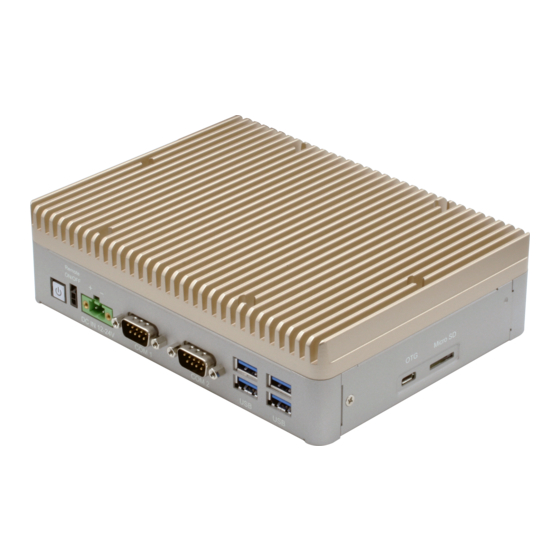
- Page 1 BOXER-8170AI Compact Fanless Embedded AI@Edge Box PC User’s Manual 1 Last Updated: July 2, 2019...
- Page 2 Copyright Notice This document is copyrighted, 2019. All rights are reserved. The original manufacturer reserves the right to make improvements to the products described in this manual at any time without notice. No part of this manual may be reproduced, copied, translated, or transmitted in any form or by any means without the prior written permission of the original manufacturer.
- Page 3 Acknowledgement All other products’ name or trademarks are properties of their respective owners. NVIDIA, the NVIDIA logo, and Jetson are trademarks of the NVIDIA Corporation Microsoft Windows is a registered trademark of Microsoft Corp. Intel, Pentium, Celeron, and Xeon are registered trademarks of Intel Corporation ...
- Page 4 Packing List Before setting up your product, please make sure the following items have been shipped: Item Quantity BOXER-8170AI Power Connector Screw Pack Wallmount bracket If any of these items are missing or damaged, please contact your distributor or sales representative immediately.
- Page 5 About this Document This User’s Manual contains all the essential information, such as detailed descriptions and explanations on the product’s hardware and software features (if any), its specifications, dimensions, jumper/connector settings/definitions, and driver installation instructions (if any), to facilitate users in setting up their product. Users may refer to the product page on AAEON.com for the latest version of this document.
- Page 6 Safety Precautions Please read the following safety instructions carefully. It is advised that you keep this manual for future references All cautions and warnings on the device should be noted. All cables and adapters supplied by AAEON are certified and in accordance with the material safety laws and regulations of the country of sale.
- Page 7 As most electronic components are sensitive to static electrical charge, be sure to ground yourself to prevent static charge when installing the internal components. Use a grounding wrist strap and contain all electronic components in any static-shielded containers. If any of the following situations arises, please the contact our service personnel: Damaged power cord or plug Liquid intrusion to the device iii.
- Page 8 FCC Statement This device complies with Part 15 FCC Rules. Operation is subject to the following two conditions: (1) this device may not cause harmful interference, and (2) this device must accept any interference received including interference that may cause undesired operation.
- Page 9 China RoHS Requirements (CN) Preface...
- Page 10 China RoHS Requirement (EN) Preface...
-
Page 11: Table Of Contents
Table of Contents Chapter 1 - Product Specifications..................1 Specifications ......................2 Product Notice ......................4 Chapter 2 – Hardware Information ..................5 Dimensions ....................... 6 Jumpers and connectors..................9 List of Jumpers ......................10 2.3.1 Setting Jumpers ..................10 2.3.2 Auto Power Button (CN1) .............. -
Page 12: Chapter 1 - Product Specifications
Chapter 1 Chapter 1 - Product Specifications... -
Page 13: Specifications
Specifications System HMP Dual Denver 2 + Quad ARM A57 Chipset 8GB LPDDR4 System Memory NVidia Jetson TX2 AI Solution HDMI 2.0 x2 Display Interface 32GB eMMC 5.1 Storage Device MicroSD 10/100/1000 Base-TX x 1 Ethernet IEEE 802.3 af PoE LAN x 4 RJ-45 x 4 for PoE+ (802.af) (Total 60W) IEEE 802.3af PoE x4 60W total power budget HDMI Type A x 2 for HDMI 2.0... - Page 14 System Power LED Indicator Linux (AAEON ACLinux 4.4, Compliance with OS Support Ubuntu 16.04) Power Supply 12~24V with 2-pin terminal block Power Requirement Mechanical Wallmount Mounting 180 mm (W) x 48 mm (H) x 136 mm (D) Dimensions (W x H x D) 6.39 lbs.
-
Page 15: Product Notice
Product Notice OTG: OTG port is ideally for flashing image only. COM1: Support 1.8 meter length cable when baud rate is 115200bps and 15 meter cable when baud rate is 9600bps. USB ports: USB ports do not support USB DVD-ROM because of file system. Storage Devices: Operating System must be installed on the eMMC drive. -
Page 16: Chapter 2 - Hardware Information
Chapter 2 Chapter 2 – Hardware Information... -
Page 17: Dimensions
Dimensions Chapter 2 – Hardware Information... - Page 18 Chapter 2 – Hardware Information...
- Page 19 Chapter 2 – Hardware Information...
-
Page 20: Jumpers And Connectors
Jumpers and connectors Chapter 2 – Hardware Information... -
Page 21: List Of Jumpers
List of Jumpers The board has a number of jumpers that allow you to configure your system to suit your application. The table below shows the function of each of the board's jumpers Label Function CN22 AT mode select 2.3.1 Setting Jumpers You can configure the board to match the needs of your application by setting jumpers. -
Page 22: Auto Power Button (Cn1)
2.3.2 Auto Power Button (CN1) Closed - AT Open - ATX (Default) Function 1-2 Open ATX (Default) 1-2 Closed Chapter 2 – Hardware Information... -
Page 23: List Of Connectors
List of Connectors The board has a number of connectors that allow you to configure your system to suit your application. The table below shows the function of each of the board's connectors. Label Function FAN connector HDMI 2 connector HDMI 1 connector POE LAN 4 (802.3af) POE LAN 3 (802.3af) - Page 24 Label Function CN27 Power In Connector CN28 COM 1 Connector CN29 COM 2 Connector Recovery switch H/W Reset switch Power switch LAN1 TX2 GIGA LAN Chapter 2 – Hardware Information...
-
Page 25: Hdmi Connector (Cn2/Cn3)
2.4.1 HDMI connector (CN2/CN3) Signal Signal HDMI_DATA2_P HDMI_DATA2_N HDMI_DATA1_P HDMI_DATA1_N HDMI_DATA0_P HDMI_DATA0_N HDMI_CLK_P HDMI_CLK_N HDMI_SCL HDMI_SDA HDMI_PWR HDMI_HDP 2.4.2 SATA PWR Port (CN8) Signal Signal Chapter 2 – Hardware Information... -
Page 26: Sata Port (Cn9)
2.4.3 SATA Port (CN9) Signal Signal SATA TX+ SATA TX- SATA RX- SATA RX+ 2.4.4 Micro SD (CN10) Signal Signal SDCARD D3 SDCARD CMD SDCARD PWR(+3.3V) SDCARD CLK SDCARD D0 SDCARD D1 SDCARD D2 SDCARD CD Chapter 2 – Hardware Information... -
Page 27: Usb 2.0 Otg Connector (Cn13)
2.4.5 USB 2.0 OTG connector (CN13) Signal Signal VBUS USB1- USB1+ 2.4.6 RTC Connector (CN14) Signal Signal Chapter 2 – Hardware Information... -
Page 28: Tx2 Module Connector (Cn15)
2.4.7 TX2 Module connector (CN15) Chapter 2 – Hardware Information... -
Page 29: Usb3.0 Connector (Cn24/Cn25)
2.4.8 USB3.0 connector (CN24/CN25) Signal Signal VBUS_1 VBUS_2 (A)D- (B)D- (A)D+ (B)D+ (A)SSRX- (B)SSRX- (A)SSRX+ (B)SSRX+ (A)SSTX- (B)SSTX- (A)SSTX+ (B)SSTX+ 2.4.9 Power in connector (CN27) Signal Signal PWR IN Chapter 2 – Hardware Information... -
Page 30: Com Port Connector (Cn28/29)
2.4.10 COM port connector (CN28/29) RS-232 Chapter 2 – Hardware Information... -
Page 31: Lan (Rj-45) Port (Lan1)
2.4.11 LAN (RJ-45) Port (LAN1) Signal Signal MDI0+ MDI0- MDI1+ MDI1- MDI2+ MDI2- MDI3+ MDI3- Chapter 2 – Hardware Information... -
Page 32: Wall Mount Assembly
Wall Mount Assembly Chapter 2 – Hardware Information... -
Page 33: Chapter 3 - Os Flash Guide
Chapter 3 Chapter 3 – OS Flash guide... -
Page 34: Force Usb Recovery Mode
Force USB Recovery Mode To place system in Force USB Recovery Mode: Power down the device and disconnect the AC adapter. The device MUST be powered OFF, not in a suspended or sleep state. Connect the Micro-B plug on the USB cable to the Recovery (USB Micro-B) Port on the device and the other end to an available USB port on the host PC. -
Page 35: Software & Bsp
Software & BSP Please follow the steps below to install the test image. (1) Download ACLinux_4.4_ACLNX44D.NV02.BOXER-8170AI.TB5.tar.gz image. Please check with your local sales or FAE for the test image. The file name may change without notice. (2) Unzip ACLinux_4.4_ACLNX44D.NV02.BOXER-8170AI.TB5.tar.gz unzip ACLinux_4.4_ACLNX44D.NV02.BOXER-8170AI.TB5.tar.gz (3) Enter bootloader folder cd bootloader (5) Enter Force USB Recovery Mode.
Need help?
Do you have a question about the Aaeon BOXER-8170AI and is the answer not in the manual?
Questions and answers