
Related Manuals for Asus AAEON BOXER-8223AI


Summary of Contents for Asus AAEON BOXER-8223AI
- Page 1 BOXER-8223AI Compact Fanless Embedded AI@Edge Box PC with NVIDIA® Jetson Nano™ User’s Manual 1 Last Updated: June 22, 2021...
- Page 2 Copyright Notice This document is copyrighted, 2021. All rights are reserved. The original manufacturer reserves the right to make improvements to the products described in this manual at any time without notice. No part of this manual may be reproduced, copied, translated, or transmitted in any form or by any means without the prior written permission of the original manufacturer.
- Page 3 Acknowledgements All other products’ name or trademarks are properties of their respective owners. NVIDIA, the NVIDIA logo, and Jetson are trademarks of the NVIDIA Corporation ⚫ ITE is a trademark of Integrated Technology Express, Inc. ⚫ IBM and VGA are trademarks of International Business Machines Corporation. ⚫...
- Page 4 Packing List Before setting up your product, please make sure the following items have been shipped: Item Quantity BOXER-8223AI ⚫ Power Connector ⚫ If any of these items are missing or damaged, please contact your distributor or sales representative immediately. Preface...
- Page 5 About this Document This User’s Manual contains all the essential information, such as detailed descriptions and explanations on the product’s hardware and software features (if any), its specifications, dimensions, jumper/connector settings/definitions, and driver installation instructions (if any), to facilitate users in setting up their product. Users may refer to the product page at AAEON.com for the latest version of this document.
- Page 6 Safety Precautions Please read the following safety instructions carefully. It is advised that you keep this manual for future references All cautions and warnings on the device should be noted. All cables and adapters supplied by AAEON are certified and in accordance with the material safety laws and regulations of the country of sale.
- Page 7 As most electronic components are sensitive to static electrical charge, be sure to ground yourself to prevent static charge when installing the internal components. Use a grounding wrist strap and contain all electronic components in any static-shielded containers. If any of the following situations arises, please the contact our service personnel: Damaged power cord or plug Liquid intrusion to the device iii.
- Page 8 FCC Statement This device complies with Part 15 FCC Rules. Operation is subject to the following two conditions: (1) this device may not cause harmful interference, and (2) this device must accept any interference received including interference that may cause undesired operation.
- Page 9 China RoHS Requirements (CN) 产品中有毒有害物质或元素名称及含量 AAEON System QO4-381 Rev.A0 有毒有害物质或元素 部件名称 铅 汞 镉 六价铬 多溴联苯 多溴二苯 醚(PBDE) (Pb) (Hg) (Cd) (Cr(VI)) (PBB) 印刷电路板 × ○ ○ ○ ○ ○ 及其电子组件 外部信号 × ○ ○ ○ ○ ○ 连接器及线材 外壳 ○...
- Page 10 China RoHS Requirement (EN) Hazardous and Toxic Materials List AAEON System QO4-381 Rev.A0 Hazardous or Toxic Materials or Elements Component Name PCB and Components Wires & Connectors for Ext.Connections Chassis CPU & RAM HDD Drive LCD Module Optical Drive Touch Control Module Battery This form is prepared in compliance with the provisions of SJ/T 11364.
-
Page 11: Table Of Contents
Table of Contents Chapter 1 - Product Specifications..................1 Specifications ......................2 Product Notice ......................4 Chapter 2 – Hardware Information ..................5 Dimensions ....................... 6 Jumpers and connectors..................7 List of Jumpers ......................8 2.3.1 Setting Jumpers ..................8 2.3.2 AT/ATX Mode Select (CN15 Pins 7-8) .......... - Page 12 Hardware Assembly ....................23 2.5.1 Expansion Card Installation ..............23 2.5.2 SIM Card Installation ................25 Chapter 3 – OS Flash Guide ....................27 Flash OS Image to System ................... 28 3.1.1 Introduction .................... 28 3.1.2 Before You Begin ................... 29 3.1.3 Flash Image to Board ................
-
Page 13: Chapter 1 - Product Specifications
Chapter 1 Chapter 1 - Product Specifications... -
Page 14: Specifications
Specifications System AI Accelerator Nvidia Jetson Nano Quad Core ARM® Cortex®-A57 MPCore Proccessor System Memory 4GB LPDDR4 Storage Device 16GB eMMC + Micro SD card slot Display Interface Output: HDMI Type A 2.0 x 1 Input: HDMI Type A 1.4 x 1 Ethernet POE PSE LAN x2 (802.3af) USB Type A x 4 for USB3.2 Gen1... - Page 15 Power Supply Power Requirement DC 12V~24V 2-pin terminal block ATX mode Mechanical Mounting Wall mount kit (default) Dimensions (W x D x H) 7.09” x 5.35” x 2.41” (180.0 mm x 136 .0 mm x 61.1 Gross Weight 4.63 lbs. (2.1 kg) Net Weight 2.87 lbs.
-
Page 16: Product Notice
Product Notice Micro-USB: Micro-USB port is designed for flashing image only. USB ports: USB ports do not support USB DVD-ROM because of file system. USB 3.2 Gen 1: USB3.2 Gen 1 is the current name for 5Gbps specification, formerly USB 3.0. -
Page 17: Chapter 2 - Hardware Information
Chapter 2 Chapter 2 – Hardware Information... -
Page 18: Dimensions
Dimensions Chapter 2 – Hardware Information... -
Page 19: Jumpers And Connectors
Jumpers and connectors Chapter 2 – Hardware Information... -
Page 20: List Of Jumpers
List of Jumpers The board has a number of jumpers that allow you to configure your system to suit your application. The table below shows the function of each of the board's jumpers Label Function CN15 (Pins 7-8) AT/ATX mode select PCIe/mSATA select 2.3.1 Setting Jumpers... -
Page 21: At/Atx Mode Select (Cn15 Pins 7-8)
2.3.2 AT/ATX Mode Select (CN15 Pins 7-8) The AT/ATX Mode Select functions by connecting pins 7 and 8 of CN15. To prevent damage to the system, do not connect pins 7 and 8 to any other pin. Open – AT Mode Closed –... -
Page 22: List Of Connectors
List of Connectors The board has a number of connectors that allow you to configure your system to suit your application. The table below shows the function of each of the board's connectors Label Function Gigabit LAN Connector HDMI Out Connector HDMI In Connector POE Gigabit LAN Connector –... -
Page 23: Lan Rj45 Port (Cn1)/ Poe Rj45 Port - Intel I210 (Cn4/Cn5)
Label Function Recovery switch Reset Switch Power Switch RS-232/RS-485 Select 2.4.1 LAN RJ45 Port (CN1)/ POE RJ45 Port – Intel i210 (CN4/CN5) Signal Signal MDI0+ MDI0- MDI1+ MDI2+ MDI2- MDI1- MDI3+ MDI3- Chapter 2 – Hardware Information... -
Page 24: Hdmi Out Connector (Cn2)
2.4.2 HDMI Out Connector (CN2) Signal Signal HDMI_DATA2_P HDMI_DATA2_N HDMI_DATA1_P HDMI_DATA1_N HDMI_DATA0_P HDMI_DATA0_N HDMI_CLK_P HDMI_CLK_N HDMI_SCL HDMI_SDA HDMI_PWR HDMI_HDP Chapter 2 – Hardware Information... -
Page 25: Hdmi In Connector (Cn3)
2.4.3 HDMI In Connector (CN3) Signal Signal HDMI_DATA2_P HDMI_DATA2_N HDMI_DATA1_P HDMI_DATA1_N HDMI_DATA0_P HDMI_DATA0_N HDMI_CLK_P HDMI_CLK_N HDMI_SCL HDMI_SDA HDMI_PWR HDMI_HDP 2.4.4 RTC Battery Connector (CN7) Signal Signal Chapter 2 – Hardware Information... -
Page 26: E-Key 2280 (Cn10)
2.4.5 M.2 E-Key 2280 (CN10) Chapter 2 – Hardware Information... -
Page 27: Jetson Nano Cpu Module Connector (Cn14)
2.4.6 Jetson Nano CPU Module Connector (CN14) Chapter 2 – Hardware Information... - Page 28 Chapter 2 – Hardware Information...
-
Page 29: Front Panel Connector (Cn15)
2.4.7 Front Panel Connector (CN15) Signal Signal Power Button Recovery Reset Latch Set Latch Set PWR LED Note: Pins 7-8 are used for setting AT/ATX Mode and Auto Power. See Ch 2.3.2 for details. 2.4.8 Micro USB 2.0 for Flash Image (CN16) Signal Signal USB1-... -
Page 30: Uart Debug Port Connector (Cn18)
2.4.9 UART Debug Port Connector (CN18) Signal Signal 3.3V UART0 TXD UART0 RXD I2C SCL I2C SDA 2.4.10 USB 3.0 Connector (CN19/20) Signal Signal VBUS_1 VBUS_2 (A)D- (B)D- (A)D+ (B)D+ (A)SSRX- (B)SSRX- (A)SSRX+ (B)SSRX+ (A)SSTX- (B)SSTX- (A)SSTX+ (B)SSTX+ Chapter 2 – Hardware Information... -
Page 31: Dc Power In Connector (Cn22)
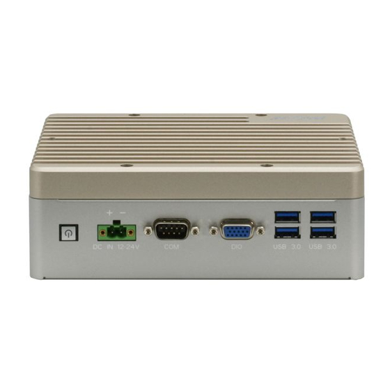
2.4.11 DC Power In Connector (CN22) Signal Signal PWR IN 2.4.12 RS-232/RS-485 Connector (CN23) RS-232 RS-422 RS-485 CAN0 L CAN0 L CAN0 L CAN0 H CAN0 H CAN0 H Note: RS-232/485 mode is controlled by SW4. See Ch 2.4.31 for setting details. Chapter 2 –... -
Page 32: External Dio Connector (Cn24)
2.4.13 External DIO Connector (CN24) Signal SYSFS GPIO +3.3V Power 37P_SPI1_MOSI_LS GPIO12 22P_SPI1_MISO_LS GPIO13 13P_SPI1_SCK_LS GPIO14 18P_SPI1_CS0_LS GPIO15 19P_SPI0_MOSI_LS GPIO16 21P_SPI0_MISO_LS GPIO17 23P_SPI0_SCK_LS GPIO18 24P_SPI0_CS0_LS GPIO19 26P_SPI0_CS1_LS GPIO20 35P_I2S0_LRCK_LS GPIO76 38P_I2S0_SDIN_LS GPIO77 40P_I2S0_SDOUT_LS GPIO78 12P_I2S0_SCLK_LS GPIO79 Chapter 2 – Hardware Information... -
Page 33: Mini Pcie Connector (Pcie1)
2.4.14 Mini PCIe Connector (PCIE1) Chapter 2 – Hardware Information... -
Page 34: Rs-232/485 Select (Sw4)
2.4.15 RS-232/485 Select (SW4) Mode 1T/1R RS-232 Reserved – No Function 1T/1R RS-485 Low Power Shutdown Enable RS-422/RS-485 bias and termination resistors Disable RS-422/RS-485 bias and termination resistors 250kbps RS-232 RS-485/RS-422 RS-232 3Mbps RS-485/RS-422 20Mbps Note: SW4 controls the RS-232/485 mode for CN23. See Ch 2.4.23 for Pin Definitions Chapter 2 –... -
Page 35: Hardware Assembly
Hardware Assembly This section details the hardware assembly steps for the BOXER-8223AI. Please read this section thoroughly before beginning installation and ensure you have all necessary components ready. A Phillips head screwdriver is required. 2.5.1 Expansion Card Installation Step 1: Remove the top chassis cover by unscrewing the six screws as shown: Chapter 2 –... - Page 36 Step 2: Locate the M.2 and Mini-Card slots as shown. Follow standard procedures for installing expansion cards. Note the location of the mounting screws. Chapter 2 – Hardware Information...
-
Page 37: Sim Card Installation
2.5.2 SIM Card Installation Step 1: Remove the bottom panel by loosening the retaining screw as shown: Step 2: Open the SIM card holder. SIM Card Holder Chapter 2 – Hardware Information... - Page 38 Step 3: Slide the SIM card into the holder, then gently press down to secure in place. Chapter 2 – Hardware Information...
-
Page 39: Chapter 3 - Os Flash Guide
Chapter 3 Chapter 3 – OS Flash Guide... -
Page 40: Flash Os Image To System
Flash OS Image to System 3.1.1 Introduction This chapter details the steps to flashing the operating system to your BOXER-8223AI NVIDIA Jetson Nano system. The operating system image can be downloaded from the product page at: https://www.aaeon.com/en/p/edge-ai-box-pc-nvidia-jetson-nano-boxer-8223ai After downloading the file, the filename will be formatted as follows: Ubuntu_18.04_{OS_IF}.{PLF_IF}.{PJ_IF}.{BN}.tar.gz is OS Information. -
Page 41: Before You Begin
3.1.2 Before You Begin Before beginning the process ensure you have the following: One host PC with operating system Ubuntu 16.04 or 18.04 Operating System image downloaded to host computer USB Cable with at least one Micro USB connector Jetson Nano Development Kit B01 module (with onboard eMMC storage); see image below for reference: Finally, on the Linux host PC, extract the image file you downloaded using the following command in terminal (remember to replace {“”} with the actual file name):... -
Page 42: Flash Image To Board
3.1.3 Flash Image to Board Step 1: Connect the host PC to the BOXER-8223AI with a Micro USB cable. Step 2: Connect the BOXER-8223AI carrier board to a 12~24V power supply. Step 3: Force Recovery Mode: Press and hold the recovery key, then press the power key. - Page 43 Step 5: You can use lsusb command on host PC to check if the device is in recovery mode: $ lsusb | grep 0955:7f21 You should see the following return if device is in recovery mode: Step 6: In terminal, enter the bootloader folder that you unzipped earlier. Step 7: Run the following command to flash the image: $ sudo ./flashall.sh Step 8: Wait for the process to complete.
-
Page 44: Appendix A - Glue Removal Procedure
Appendix A Appendix A – Glue Removal Procedure... -
Page 45: Removing Glue From Your System
Removing Glue from Your System To protect components from damage and ensure proper operation out of the box, glue may have been applied to some cables or connectors to keep them in place during shipping. This glue must be removed before attempting to swap components or perform maintenance. - Page 46 Step 1: Using an eyedropper or bottle as shown above, apply a few drops of alcohol to the glue. Step 2: Allow the alcohol to soak for 10 seconds, then use a cotton swab or cotton with anti-static tweezers to evenly rub the alcohol over the glue. Step 3: Let soak for 10 more seconds, then use anti-static tweezers to remove the glue.
- Page 47 If you encounter any issues or need support, please contact your AAEON representative or visit our Support Page at AAEON.com Appendix A – Glue Removal Procedure...
Need help?
Do you have a question about the AAEON BOXER-8223AI and is the answer not in the manual?
Questions and answers