
Related Manuals for Asus AAEON BOXER-8240AI


Summary of Contents for Asus AAEON BOXER-8240AI
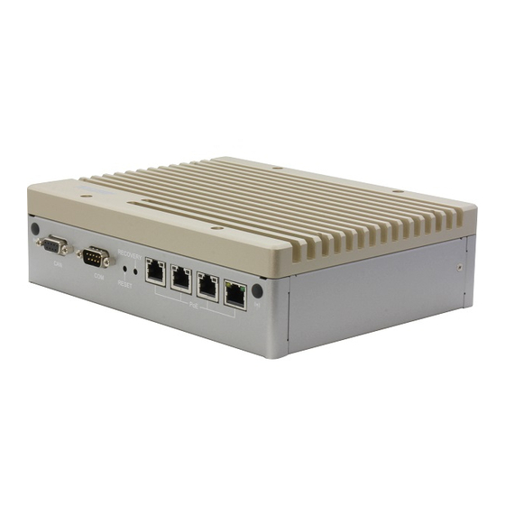
- Page 1 BOXER-8240AI Compact Fanless Embedded AI@Edge Box PC with NVIDIA® Jetson AGX Xavier™ User’s Manual 1 Last Updated: December 8, 2020...
- Page 2 Copyright Notice This document is copyrighted, 2020. All rights are reserved. The original manufacturer reserves the right to make improvements to the products described in this manual at any time without notice. No part of this manual may be reproduced, copied, translated, or transmitted in any form or by any means without the prior written permission of the original manufacturer.
- Page 3 Acknowledgements All other products’ name or trademarks are properties of their respective owners. NVIDIA®, the NVIDIA logo, Jetson™, Jetson Xavier™, and Jetson AGX Xavier™ ⚫ are trademarks of the NVIDIA Corporation ITE is a trademark of Integrated Technology Express, Inc. ⚫...
- Page 4 Packing List Before setting up your product, please make sure the following items have been shipped: Item Quantity BOXER-8240AI ⚫ If any of these items are missing or damaged, please contact your distributor or sales representative immediately. Preface...
- Page 5 About this Document This User’s Manual contains all the essential information, such as detailed descriptions and explanations on the product’s hardware and software features (if any), its specifications, dimensions, jumper/connector settings/definitions, and driver installation instructions (if any), to facilitate users in setting up their product. Users may refer to the product page at AAEON.com for the latest version of this document.
- Page 6 Safety Precautions Please read the following safety instructions carefully. It is advised that you keep this manual for future references All cautions and warnings on the device should be noted. All cables and adapters supplied by AAEON are certified and in accordance with the material safety laws and regulations of the country of sale.
- Page 7 As most electronic components are sensitive to static electrical charge, be sure to ground yourself to prevent static charge when installing the internal components. Use a grounding wrist strap and contain all electronic components in any static-shielded containers. If any of the following situations arises, please the contact our service personnel: Damaged power cord or plug Liquid intrusion to the device iii.
- Page 8 FCC Statement This device complies with Part 15 FCC Rules. Operation is subject to the following two conditions: (1) this device may not cause harmful interference, and (2) this device must accept any interference received including interference that may cause undesired operation.
- Page 9 China RoHS Requirements (CN) 产品中有毒有害物质或元素名称及含量 AAEON System QO4-381 Rev.A0 有毒有害物质或元素 部件名称 铅 汞 镉 六价铬 多溴联苯 多溴二苯 醚(PBDE) (Pb) (Hg) (Cd) (Cr(VI)) (PBB) 印刷电路板 × ○ ○ ○ ○ ○ 及其电子组件 外部信号 × ○ ○ ○ ○ ○ 连接器及线材 外壳 ○...
- Page 10 China RoHS Requirement (EN) Hazardous and Toxic Materials List AAEON System QO4-381 Rev.A0 Hazardous or Toxic Materials or Elements Component Name PCB and Components Wires & Connectors for Ext.Connections Chassis CPU & RAM HDD Drive LCD Module Optical Drive Touch Control Module Battery This form is prepared in compliance with the provisions of SJ/T 11364.
-
Page 11: Table Of Contents
Table of Contents Chapter 1 - Product Specifications..................1 Specifications ......................2 Product Notice ......................4 Chapter 2 – Hardware Information ..................5 Dimensions ....................... 6 Jumpers and connectors..................8 List of Jumpers ......................9 2.3.1 Setting Jumpers ..................9 2.3.2 AT/ATX Mode Select (CN16 Pins 5-6) .......... - Page 12 2.4.17 SATA Connector with Power (CN31) ..........24 2.4.18 COM5 Connector (CN32) ..............25 2.4.19 CAN BUS Connector (CN33) .............. 26 2.4.20 uSD (microSD) Connector (J1) ............27 2.4.21 RS-232/422/485 Select (SW4, SW5) ..........28 Hardware Assembly ....................29 Chapter 3 – OS Flash Guide ....................32 Before Installation ....................
-
Page 13: Chapter 1 - Product Specifications
Chapter 1 Chapter 1 - Product Specifications... -
Page 14: Specifications
Specifications System AI Accelerator Nvidia AGX Xavier 8-core ARM v8.2 64bit CPU, 8MB L2 + 4MB L3 System Memory 32 GB 256-Bit LPDDR4 x 1 137 GB/s Storage Device 32GB eMMC M.2 Key M 2280 x 1 (PCIe[x4]) uSD (microSD) slot x 1 Display Interface HDMI 2.0 Ethernet... - Page 15 System Expansion Expansion header 40-pin (UART + SPI + I2C + I2S + DMIC + GPIOs) USB 2.0 header x 1 (Optional, circuit reserved) M.2 Key E 2230 x1 for Wi-Fi/Bluetooth (PCIe[x1] + USB) M.2 Key M 2280 x1 (PCIe[x4]) JTAG Connector Indicator Power LED x1 OS Support...
-
Page 16: Product Notice
Product Notice Micro-USB: Micro-USB port is for flashing image only. USB ports: USB ports do not support USB DVD ROM because of file system. USB 3.2 Gen 1: USB 3.2 Gen 1 is the current name for 5Gbps specification, formerly USB 3.0. -
Page 17: Chapter 2 - Hardware Information
Chapter 2 Chapter 2 – Hardware Information... -
Page 18: Dimensions
Dimensions Chapter 2 – Hardware Information... - Page 19 System I/O Layout Chapter 2 – Hardware Information...
-
Page 20: Jumpers And Connectors
Jumpers and connectors Chapter 2 – Hardware Information... -
Page 21: List Of Jumpers
List of Jumpers The board has a number of jumpers that allow you to configure your system to suit your application. The table below shows the function of each of the board's jumpers Label Function CN16 (Pins 5-6) AT/ATX mode select 2.3.1 Setting Jumpers You can configure your system to match the needs of your application by setting... -
Page 22: At/Atx Mode Select (Cn16 Pins 5-6)
2.3.2 AT/ATX Mode Select (CN16 Pins 5-6) The AT/ATX Mode Select functions by connecting pins 5 and 6 of CN16. To prevent damage to the system, do not connect pins 5 and 6 to any other pin. Open – ATX Mode Closed –... -
Page 23: List Of Connectors
List of Connectors The board has a number of connectors that allow you to configure your system to suit your application. The table below shows the function of each of the board's connectors Label Function COM1 Connector (/dev/ttyTHS1) UART3 for Debug PoE Gigabit LAN Connector (PHY) PoE Gigabit LAN Connector (i210) PoE Gigabit LAN Connector (i210) -
Page 24: Com1 Connector (Cn1)
Label Function CN32 COM5 Connector (/dev/ttyTHS5) CN33 CAN BUS Connector uSD (microSD) Connector Recovery Switch Reset Switch Power Switch RS-232/422/485 Select (/dev/ttyTHS1) RS-232/422/485 Select (/dev/ttyTHS5) Jetson AGX Xavier CPU Connector 2.4.1 COM1 Connector (CN1) RS-232 RS-422 RS-485 Chapter 2 – Hardware Information... -
Page 25: Uart Debug Connector (Cn3)
2.4.2 UART Debug Connector (CN3) Pin Name Signal Type UART3 TXD UART3 RXD RXD_3 RS-232 TXD_3 RS-232 I2C SCL 3.3V I2C SDA 3.3V Chapter 2 – Hardware Information... -
Page 26: Poe Gigabit Lan Connector (Cn4/Cn5/Cn6/Cn7)
2.4.3 PoE Gigabit LAN Connector (CN4/CN5/CN6/CN7) Signal Signal MDI0+ MDI0- MDI1+ MDI1- MDI2+ MDI2- MDI3+ MDI3- 2.4.4 JTAG Debug Connector (CN11) Signal Signal +1.8V JTAG_TMS JTAG_TCK JTAG_TDO JTAG_TDI 10K PULL-UP 1.8V SYS_RST# Chapter 2 – Hardware Information... -
Page 27: E-Key Slot (2230) (Cn12)
2.4.5 M.2 E-Key Slot (2230) (CN12) Chapter 2 – Hardware Information... -
Page 28: 40-Pin Expansion Dio Header (Cn13)
2.4.6 40-Pin Expansion DIO Header (CN13) Note: Pins 29, 31, 33, 37 used by CAN BUS Connector (CN33). 2.4.7 RTC Battery Connector (CN14) Signal Signal Chapter 2 – Hardware Information... -
Page 29: Front Panel Connector (Cn16)
2.4.8 Front Panel Connector (CN16) Signal Signal Recovery Reset Power Button GND (see note) GND (see note) CVB_STBY System_OC# +3.3V_AO +5V_AO Note: Pin 5 and 6 are used for setting AT/ATX Power Mode. See Chapter 2.3.2 for information. To prevent damage to your system, do not connect Pins 5 and 6 with any other pin. -
Page 30: Audio Connector (Cn19)
2.4.9 Audio Connector (CN19) Signal Signal MIC1 MIC2 GPIO4 HPO_R MIC_IN_DET HPO_L GPIO3 GPIO3: Headphone or Jack detection. GPIO4: Pre-sense – detects if audio dongle is connected to header. 2.4.10 DP Connector (CN22) Signal Signal ML_Lane0_P ML_Lane0_N ML_Lane1_P ML_Lane1_N ML_Lane2_P ML_Lane2_N ML_Lane3_P Chapter 2 –... -
Page 31: Hdmi Connector (Cn23)
Signal Signal ML_Lane3_N AUX_CH_P AUX_CH_N DP_HDP DP_POWER(3.3V) 2.4.11 HDMI Connector (CN23) Signal Signal HDMI_DATA2_P HDMI_DATA2_N HDMI_DATA1_P HDMI_DATA1_N HDMI_DATA0_P HDMI_DATA0_N HDMI_CLK_P HDMI_CLK_N HDMI_SCL HDMI_SDA HDMI_PWR HDMI_HDP Chapter 2 – Hardware Information... -
Page 32: Usb 3.2 + Usb 2.0 Combo Connector (Cn24)
2.4.12 USB 3.2 + USB 2.0 Combo Connector (CN24) Signal Signal USB 3.2 (Bottom) USB 2.0 (Top) VBUS_1 VBUS_2 (A)D- (B)D- (A)D+ (B)D+ (A)SSRX- (A)SSRX+ (A)SSTX- (A)SSTX+ 2.4.13 DC-In Power Connector (CN26) Signal Signal PWR_IN Chapter 2 – Hardware Information... -
Page 33: Usb 3.0 Type C Connector (Cn27/Cn28)
2.4.14 USB 3.0 Type C Connector (CN27/CN28) Signal Signal (A)SSTX+ (B)SSRX+ (A)SSTX- (B)SSRX- VBUS_1 VBUS_2 SBU2 (A)D+ (B)D- (A)D- (B)D+ SBU1 VBUS_1 VBUS_2 (A)SSRX- (B)SSTX- (A)SSRX+ (B)SSTX+ Chapter 2 – Hardware Information... -
Page 34: Micro Usb (Flash & Otg) (Cn29)
2.4.15 Micro USB (Flash & OTG) (CN29) Signal Signal USB1- USB1+ Chapter 2 – Hardware Information... -
Page 35: M-Key Slot (2280) (Cn30)
2.4.16 M.2 M-Key Slot (2280) (CN30) Chapter 2 – Hardware Information... -
Page 36: Sata Connector With Power (Cn31)
2.4.17 SATA Connector with Power (CN31) Signal Signal SATA Signal SATA Power and Control Chapter 2 – Hardware Information... -
Page 37: Com5 Connector (Cn32)
2.4.18 COM5 Connector (CN32) RS-232 RS-422 RS-485 Chapter 2 – Hardware Information... -
Page 38: Can Bus Connector (Cn33)
2.4.19 CAN BUS Connector (CN33) Signal Signal CAN0_H CAN0_L CAN1_H CAN1_L Chapter 2 – Hardware Information... -
Page 39: Usd (Microsd) Connector (J1)
2.4.20 uSD (microSD) Connector (J1) uSD (microSD) Card Pin (Card) Pin (Connector) Function DAT2 CD/DAT3 DAT0 DAT1 Chapter 2 – Hardware Information... -
Page 40: Rs-232/422/485 Select (Sw4, Sw5)
2.4.21 RS-232/422/485 Select (SW4, SW5) Mode 1T/1R RS-232 1T/1R RS-422 1T/1R RS-485 Low power shutdown Enable RS-422/RS-485 bias and termination resistors. Disable RS-422/RS-485 bias and termination resistors. 250kbps for RS-232 and RS-485/RS-422 RS-232 to 3Mbps and RS-485/RS-422 to 20Mbps Chapter 2 – Hardware Information... -
Page 41: Hardware Assembly
Hardware Assembly M.2 E-Key (2230) Installation The M.2 E-Key (2230) slot can be accessed by removing the top cover/heatsink as shown above. Chapter 2 – Hardware Information... - Page 42 The M.2 M-Key (2280) slot and 2.5” HDD/SSD bay can be accessed via removable covers on the bottom panel of the BOXER-8240AI system as shown in the following steps. 2.5” HDD or SSD Installation Note: To ensure proper operation, make sure to secure 2.5” drive to drive chassis with four screws.
- Page 43 M.2 M-Key (2280) Installation Chapter 2 – Hardware Information...
-
Page 44: Chapter 3 - Os Flash Guide
Chapter 3 Chapter 3 – OS Flash Guide... -
Page 45: Before Installation
Before Installation Before starting the process make sure your BOXER-8240AI system is turned off and the power in is disconnected. You will need a host PC running Ubuntu 16.04 or 18.04, and make sure the NVIDIA Jetson AGX Xavier module is installed onto the BOXER-8240AI carrier board/ system. -
Page 46: Connecting To Pc/Force Recovery Mode
Connecting to PC/Force Recovery Mode On Host Computer, open Linux terminal and enter the following command to extract compressed OS image files (file name may vary): $ tar -zxvf ACLinux_4.9_ACLNX49D.NV04.BOXER-8240AI.2.tar.gz Next, perform the following steps to force the system to start in USB Recovery Mode: Connect the Micro-USB plug on the USB cable to the Recovery Port on the BOXER-8240AI and the other end to an available USB port on the host PC. -
Page 47: Flash Image To Board
Flash Image to Board Use the following steps to flash the OS to the BOXER-8240AI. Open terminal on Ubuntu host PC, then access the bootloader folder you extracted in the previous section. Enter the following command in terminal to flash the image: $ sudo ./flashall.sh Wait as the image is installed. -
Page 48: Chapter 4 - Aclinux User Guide
Chapter 4 Chapter 4 – ACLinux User Guide Chapter 3 – OS Flash guide... -
Page 49: Introduction
Introduction ACLinux is the customized Linux operating system designed and optimized for use with AAEON systems powered by NVIDIA Jetson SoCs. ACLinux is compatible with Ubuntu and comes with the NVIDIA Jetson SDK pre-installed. For BOXER-8240AI, it also features NVIDIA Jetpack 4.4 preinstalled with the following SDK tools: Jetpack 4.4 All built-in Jetson SDK Components: CUDA Toolkit for L4T v10.2... -
Page 50: Aclinux Updates
ACLinux Updates AAEON maintains updated versions of ACLinux on the product page, which follow updates to the NVIDIA Jetpack software. Contact your AAEON representative or visit the product page to download the latest version of ACLinux for your system: https://www.aaeon.com/en/p/ai-embedded-box-pc-nvidia-jetson-agx-xavier-boxer-82 40ai ACLinux Ubuntu Compatibility ACLinux is designed to offer compatibility with Ubuntu. -
Page 51: Known Issues
ACLinux GUI based on LXDE (left) vs Ubuntu Gnome GUI (right). Known Issues The storage device where the OS is installed must have at lease 10 KB of free space. If there is less than 10 KB on the storage device, the OS will not be able to complete the login process, and the system will be stuck in a reboot loop. -
Page 52: Power Mode Control For Boxer-8420Ai
Power Mode Control for BOXER-8420AI The NVIDIA Jetson AGX Xavier supports multiple power modes to give users a range of performance options to best suit their application’s needs. To change power mode, look up the Mode ID of the corresponding power mode according to the chart below. Default Mode ID is 7 (15W with max CPU freq. - Page 53 Alternatively, the power mode can be managed and changed remotely with a third-party JTOP tool (usually requires between 200 MB and 300 MB storage space). To install the JTOP tool, enter the following commands in terminal: $ sudo apt-get install -y python3-pip $ sudo python3 -m pip install jetson-stats Once the tool is installed, it can be accessed in terminal with the command: $ sudo jtop...
Need help?
Do you have a question about the AAEON BOXER-8240AI and is the answer not in the manual?
Questions and answers