
Related Manuals for Daikin FVXD60FV2CW


Summary of Contents for Daikin FVXD60FV2CW
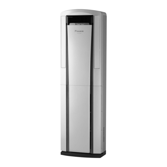
- Page 1 Si06-760 REMOVAL PROCEDURE S E R V I C E M A N U A L 6.0/7.1 kW Class Indoor Unit Inverter Floor Standing Type...
- Page 2 Service Manual Removal Procedure Indoor Unit Heat Pump FVXD60FV2CW FVXD60FV2CN FVXD71FV2CW FVXD71FV2CN FVXS71FV2CN FVXS71FV2CW...
-
Page 3: Table Of Contents
Si06-760 Table of Contents 1. Removal of Air Filter................2 2. Removal of Suction Grille................4 3. Removal of Control PCB .................5 4. Removal of Piping Cover ................9 5. Removal of Electrical Box ..............10 6. Removal of Fan Rotor / Fan Motor............11 7. -
Page 4: Removal Of Air Filter
Removal of Air Filter Si06-760 1. Removal of Air Filter Procedure Warning Be sure to wait 10 minutes or more after turning off all power supplies before disassembling work. Step Procedure Points 1. Features Fixing Screws Display Vertical Blades Air Outlet Horizontal Blades (Inside) - Page 5 Si06-760 Removal of Air Filter Step Procedure Points 2. Remove the air filter. Warning : Put your fingers on the Make sure the vertical blades right and left air inlets, are closed. Otherwise the air and open the suction filter cannot be pulled out. grille.
-
Page 6: Removal Of Suction Grille
Removal of Suction Grille Si06-760 2. Removal of Suction Grille Procedure Warning Be sure to wait 10 minutes or more after turning off all power supplies before disassembling work. Step Procedure Points 1. Remove the suction grille. Open the suction grille, and loosen the 2 screws. -
Page 7: Removal Of Control Pcb
Si06-760 Removal of Control PCB 3. Removal of Control PCB Procedure Warning Be sure to wait 10 minutes or more after turning off all power supplies before disassembling work. Step Procedure Points 1. Remove the control PCB. Remove the suction grille. Remove the 2 screws (top and bottom on the left) off the electrical... - Page 8 Removal of Control PCB Si06-760 Step Procedure Points Disconnect the connector for fan motor [S1] [S1]. (R18637) Disconnect the connectors [S21] [S35]. [S21] [S35] (R18638) Disconnect the connectors [S26] [S28] and the connector for indoor heat exchanger thermistor [S32]. [S32] [S28] [S26] (R18639) Disconnect the...
- Page 9 Si06-760 Removal of Control PCB Step Procedure Points Remove the screw and disconnect the earth Earth Terminal Screw terminal. Green / Yellow (R10046) Release the room temperature thermistor from the holder. Holder Room Temperature Thermistor (R4634) Pull out the room temperature thermistor from the hole of the electrical box.
- Page 10 Removal of Control PCB Si06-760 Step Procedure Points Pull the 3 PCB spacers Preferably use long-nose out of the control PCB. pliers to easily draw out the PCB spacers. Electrical box (R18528) Section view PCB spacers (3) (R18527) Remove the control PCB.
-
Page 11: Removal Of Piping Cover
Si06-760 Removal of Piping Cover 4. Removal of Piping Cover Procedure Warning Be sure to wait 10 minutes or more after turning off all power supplies before disassembling work. Step Procedure Points 1. Detach the piping cover. Remove the suction grille. Remove the screw and detach the piping cover. -
Page 12: Removal Of Electrical Box
Removal of Electrical Box Si06-760 5. Removal of Electrical Box Procedure Warning Be sure to wait 10 minutes or more after turning off all power supplies before disassembling work. Step Procedure Points 1. Remove the electrical box. Remove the electrical box cover. -
Page 13: Removal Of Fan Rotor / Fan Motor
Si06-760 Removal of Fan Rotor / Fan Motor 6. Removal of Fan Rotor / Fan Motor Procedure Warning Be sure to wait 10 minutes or more after turning off all power supplies before disassembling work. Step Procedure Points 1. Detach the fan rotor. Remove the suction grille, electrical box and piping fixture. - Page 14 Removal of Fan Rotor / Fan Motor Si06-760 Step Procedure Points 2. Detach the fan motor. <Attention in the fan motor installation> Remove the 2 screws Before you tighten screws, be on the left side and sure that the rubber vibration remove the fan harness isolators (front, back) of the fan cover.
- Page 15 Si06-760 Removal of Fan Rotor / Fan Motor Step Procedure Points Cut the clamp and release the harness from the fan motor Clamp stand. Remove the 4 screws and remove the fan motor from the stand. Fan motor stand Screws Screws Fan motor (R18537)
-
Page 16: Removal Of Front Panel
Removal of Front Panel Si06-760 7. Removal of Front Panel Procedure Warning Be sure to wait 10 minutes or more after turning off all power supplies before disassembling work. Step Procedure Points 1. Detach the front panel. Release the 2 hooks in the middle of the Shaft vertical blade. - Page 17 Si06-760 Removal of Front Panel Step Procedure Points Lift the front panel up to undo the 4 hooks and Hooks pull it out. Hooks (R4652) Removal Procedure...
-
Page 18: Removal Of Display Pcb
Removal of Display PCB Si06-760 8. Removal of Display PCB Procedure Warning Be sure to wait 10 minutes or more after turning off all power supplies before disassembling work. Step Procedure Points 1. Remove the display PCB. Take out the display PCB from behind the front panel. -
Page 19: Removal Of Indoor Heat Exchanger
Si06-760 Removal of Indoor Heat Exchanger 9. Removal of Indoor Heat Exchanger Procedure Warning Be sure to wait 10 minutes or more after turning off all power supplies before disassembling work. Step Procedure Points 1. Detach the indoor heat exchanger. Detach the front panel. - Page 20 Removal of Indoor Heat Exchanger Si06-760 Step Procedure Points Remove the 4 screws of the indoor heat exchanger. Screws Screws (R4658) Lift up and remove the indoor heat exchanger. Indoor heat exchanger (R18524) Removal Procedure...
- Page 21 Si06-760 Removal of Indoor Heat Exchanger Step Procedure Points Loosen the 4 screws to remove the fin guard. Metal plates When replacing indoor heat exchanger, detach the metal plates and Indoor heat exchanger attach them to the new one. Fin guard Screws (R18525) Removal Procedure...
- Page 22 Revision History Month / Year Version Revised contents 07 / 2013 Si06-760 First edition...
- Page 23 Improper installation can result in water or refrigerant leakage, electrical shock, fire or explosion. Use only those parts and accessories supplied or specified by Daikin. Ask a qualified installer or contractor to install those parts and accessories. Use of unauthorised parts and accessories or improper installation of parts and accessories can result in water or refrigerant leakage, electrical shock, fire or explosion.
Need help?
Do you have a question about the FVXD60FV2CW and is the answer not in the manual?
Questions and answers