Table of Contents
Advertisement
Quick Links
Advertisement
Table of Contents

Subscribe to Our Youtube Channel
Related Manuals for Pepperl+Fuchs FIELDBUS


Summary of Contents for Pepperl+Fuchs FIELDBUS
- Page 1 PROCESS AUTOMATION MANUAL COMPACT FIELDBUS POWER HUB, GENERIC INTERFACE...
- Page 2 Compact Fieldbus Power Hub,Generic Interface With regard to the supply of products, the current issue of the following document is ap- plicable: The General Terms of Delivery for Products and Services of the Electrical Indus- try, published by the Central Association of the Electrical Industry (Zentralverband Elektrotechnik und Elektroindustrie (ZVEI) e.V.) in its most recent version as well as the...
-
Page 3: Table Of Contents
Compact Fieldbus Power Hub,Generic Interface Safety ................... 5 Validity....................5 Symbols used..................5 System Operator and Personnel ............5 Pertinent Laws, Standards, Directives, and further Documentation5 Delivery, Transport and Storage ............6 Marking ....................6 Intended Use ..................7 Mounting and Installation..............7 1.8.1... - Page 4 Shielding and Grounding ..............18 Connection Layout ................18 3.3.1 Connections ..................20 Segment Termination .................21 Fieldbus Power Hub Basic Diagnostics ......... 22 Thermal Dissipation ..............23 Appendix ................... 25 Ordering Information................25 Electromagnetic Compatibility Verification in Accordance with EC Council Legislation Directive 2004/108/EC........25...
-
Page 5: Safety
Compact Fieldbus Power Hub,Generic Interface Safety Safety Validity Specific processes and instructions in this document require special precautions to guarantee the safety of the operating personnel. Symbols used This document contains information that you must read for your own personal safety and to avoid property damage. -
Page 6: Delivery, Transport And Storage
Compact Fieldbus Power Hub,Generic Interface Safety Delivery, Transport and Storage Check the packaging and contents for damage. Check if you have received every item and if the items received are the ones you ordered. Keep the original packaging. Always store and transport the device in the original packaging. -
Page 7: Intended Use
Connection or disconnection of energized non-intrinsically-safe circuits is only permitted in the absence of a hazardous atmosphere. It is necessary to pay particular attention to the type of Fieldbus Power Supply selected for use on the Power Hub. This determines the type of Zone 2/Div. 2 installations and certified field... -
Page 8: Ex Ic
For example, the output voltage must be equal or less than the maximum voltage of the connected field devices. Requirements for all used fieldbus products in Zone 2 installations are summarized in the manual: "Using Pepperl+Fuchs fieldbus equipment in Zone 2 hazardous area environment". -
Page 9: Repair And Maintenance
Compact Fieldbus Power Hub,Generic Interface Safety 1.10 Repair and Maintenance The devices must not be repaired, changed or manipulated. If there is a defect, the product must always be replaced with an original device. 1.11 Disposal Disposing of devices, packaging material, and possibly contained batteries must be in... -
Page 10: Specification
Measurement data and alarms are transmitted to the control room. They bring visibility to the fieldbus physical layer, so it can be treated as an active component in Plant Asset Management systems. Operators are enabled to decide on proactive measures to avoid... -
Page 11: System Components
The motherboard MBHC-FB-8R enables the redundant supply of eight segments and the connection of the FOUNDATION Fieldbus H1 Host system. 16 sockets hold the power supply modules, with two each supplying one of the eight segments redundantly. Two extra sockets hold diagnostic modules. -
Page 12: Diagnostic Modules
For further information please refer to the manual Advanced Diagnostic Module HD2-DM-A. Advanced Diagnostic Module Relay Output The ADM relay output is a tool for permanently monitoring the fieldbus physical layer. Using DIP switches, limit ranges can be configured for each physical layer parameter monitored. -
Page 13: Component Identity
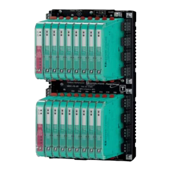
Compact Fieldbus Power Hub,Generic Interface Specification Component Identity Host connection Power modules Diagnostic modules Bulk power connections with mounted connector cover for Ex ic installations Screen/ground connection clamp Common alarm voltage-free contact and Diagnostic bus connection Trunk connection ACC-MB-HSK Screening/earthing kit... - Page 14 Compact Fieldbus Power Hub,Generic Interface Specification Motherboard Types MBHC-FB-8R Supply Rated voltage 19.2 ... 35 V SELV/PELV Rated current 16 A Power loss typ. 0.4 W per segment Terminating resistor 100 integrated Indicators/operating means Fault signal VFC alarm 1 A, 50 V DC, normally closed Isolated Power Supply Module Type HCD2-FBPS-1.500...
- Page 15 LED Seg 1...4 yellow: bus activity; yellow 2 Hz flashing: Maintenance required; red 2 Hz flashing: specification limit violated; red: hardware error DIP-switch fieldbus type , redundant supply , Signal level , Noise level , Jitter Accessories ACC-MB-HDC Diagnostic link cable Coupling the diagnostic bus between two motherboards, length 6 cm.
-
Page 16: Dimensional Drawings
Compact Fieldbus Power Hub,Generic Interface Specification Dimensional Drawings 150 mm (5.9") 268 mm (10.5") 180 mm (7.1") 195 mm (7.7") All dimensions in millimeters (inches) and without tolerance indication. -
Page 17: Installation And Commissioning
Installation and Commissioning Installation and Commissioning Mounting and Dismounting Mounting of Fieldbus Motherboards on DIN Mounting Rail To mount a motherboard on a DIN mounting rail, proceed as follows: 1. Place the motherboard on the mounting rail. 2. Tighten the two fastening screws to attach the motherboard on the DIN rail. -
Page 18: Shielding And Grounding
Compact Fieldbus Power Hub,Generic Interface Installation and Commissioning Dismounting Modules from the Motherboard To dismount a module from the motherboard, proceed as follows: Pull up the red Quick Lok Bars on each side of the module and carefully lift off the entire module. - Page 19 Compact Fieldbus Power Hub,Generic Interface Installation and Commissioning Connecting the Trunk The motherboard is connected to the trunk line via designated screw terminals. See "Cable and Connection Information" on page 18. Tr un k Segment + Segment - Shield connection...
-
Page 20: Connections
Compact Fieldbus Power Hub,Generic Interface Installation and Commissioning Connecting the Host The motherboard is connected to the host system via designated screw terminals. Tr un k Host + Host - Shield Grounding The motherboard is connected to the earth via designated screws. -
Page 21: Segment Termination
Installation and Commissioning Installation Requirements for Ex ic Installations If the fieldbus Power Hub should be used within an intrinsically safe installation (Ex ic), ensure that the following installation requirements are fulfilled: Mounting the Connector Cover ACC-MB-CC for Ex ic Installations... -
Page 22: Fieldbus Power Hub Basic Diagnostics
Compact Fieldbus Power Hub,Generic Interface Fieldbus Power Hub Basic Diagnostics Fieldbus Power Hub Basic Diagnostics The FieldConnex Power Hub system provides integrated self-supervision functionality located ® within the Power Modules and the Motherboards. Additionally, a Basic Diagnostic Module is available to monitor the bulk power supply status and compatibility of the mounted Power Modules in redundant systems. -
Page 23: Thermal Dissipation
Compact Fieldbus Power Hub,Generic Interface Thermal Dissipation Thermal Dissipation Each Power Supply dissipates, i.e., loses energy in form of heat. The graphs below illustrate typical power dissipation values in watt (W) for one segment including motherboard power losses, for given output currents and supply voltages. - Page 24 Compact Fieldbus Power Hub,Generic Interface Thermal Dissipation Thermal Dissipation of HCD2-FBPS-1.23.500, including motherboard HCD2-FBPS-1.23.500 Power dissipation in SIMPLEX configuration per segment 35 V 19,2 V 24 V Segment current in [mA] HCD2-FBPS-1.23.500 Power dissipation in REDUNDANT configuration per segment 35 V...
-
Page 25: Appendix
Compact Fieldbus Power Hub,Generic Interface Appendix Appendix Ordering Information Designation Description HCD2-FBPS-1.500 General purpose isolated FieldConnex Power Supply ® Module with 28 ... 30 V DC and 500 mA output. HCD2-FBPS-1.23.500 Ex ic, Ex nL isolated FieldConnex Power Supply Module ®... -
Page 26: Referenced Documents
EN 55011 RF conducted Class A emission RF radiated emission Class A Referenced Documents Manual: "Using Pepperl+Fuchs fieldbus equipment in Zone 2 hazardous area ■ environment" Selection table: Conformity of FieldConnex Power Hub modules and Motherboards to ® ■... - Page 27 PROCESS AUTOMATION – PROTECTING YOUR PROCESS Worldwide Headquarters Pepperl+Fuchs GmbH 68307 Mannheim · Germany Tel. +49 621 776-0 E-mail: info@de.pepperl-fuchs.com For the Pepperl+Fuchs representative closest to you check www.pepperl-fuchs.com/contact www.pepperl-fuchs.com Subject to modifications / TDOCT-1858C_ENG Copyright PEPPERL+FUCHS • Printed in Germany 01/2013...
Need help?
Do you have a question about the FIELDBUS and is the answer not in the manual?
Questions and answers