
Subscribe to Our Youtube Channel
Related Manuals for Pepperl+Fuchs M-LB 2000 Series


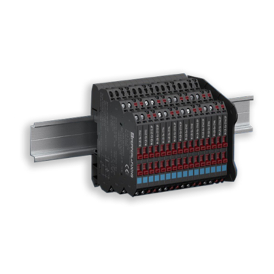
Summary of Contents for Pepperl+Fuchs M-LB 2000 Series
- Page 1 PROCESS AUTOMATION MANUAL M-LB-(Ex-)2000-System Surge Protection Barriers ISO9001...
- Page 2 M-LB-(Ex-)2000-System – Surge Protection Barriers With regard to the supply of products, the current issue of the following document is applicable: The General Terms of Delivery for Products and Services of the Electrical Industry, published by the Central Association of the Electrical Industry (Zentralverband Elektrotechnik und Elektroindustrie (ZVEI) e.V.) in its most recent version as well as the supplementary clause: "Expanded reservation of proprietorship"...
-
Page 3: Table Of Contents
M-LB-(Ex-)2000-System – Surge Protection Barriers Content Introduction ........... 4 Content of this Document. -
Page 4: Introduction
M-LB-(Ex-)2000-System – Surge Protection Barriers Introduction Introduction Content of this Document This document contains information that you need in order to use your product throughout the applicable stages of the product life cycle. These can include the following: • Product identification •... -
Page 5: Symbols Used
M-LB-(Ex-)2000-System – Surge Protection Barriers Introduction Symbols Used This document contains symbols for the identification of warning messages and of informative messages. Warning Messages You will find warning messages, whenever dangers may arise from your actions. It is mandatory that you observe these warning messages for your personal safety and in order to avoid property damage. -
Page 6: Product Specifications
M-LB-(Ex-)2000-System – Surge Protection Barriers Product Specifications Product Specifications Function Surge protection barriers protect C&I circuits against voltage surges caused by lightning or switching operations. The M-LB-(Ex-)2000 surge protection system offers a large number of surge protection barriers for a wide variety of applications: •... -
Page 7: Application
M-LB-(Ex-)2000-System – Surge Protection Barriers Product Specifications Application The following illustrations show typical applications in connection with isolators and zener barriers. Field side Control side Additional surrounding enclosure 24 V 250 Ω 24 V DC Power Rail Protected Surge protection barrier Surge protection barrier Isolator Protected... - Page 8 M-LB-(Ex-)2000-System – Surge Protection Barriers Product Specifications 2.2.1 Surge Protection Barriers for Grounded Signal Lines Surge protection barriers for grounded signal lines provide a defined protection level from line to earth by connecting the signal lines to earth via suppressor diodes. Use this surge protection barrier if the apparatus to be protected is not isolated from earth, e.
-
Page 9: Working Voltage
M-LB-(Ex-)2000-System – Surge Protection Barriers Product Specifications Working Voltage To ensure the best possible protection level, 2 different voltage versions are available. • Rated voltage U = 24 V DC, maximum continuous operating voltage U = 30 V DC The typical area of application for these surge protection barriers are 24 V signal loops, such as 4 mA …... -
Page 10: Surge Protection Barrier
M-LB-(Ex-)2000-System – Surge Protection Barriers Product Specifications Surge Protection Barrier The device limits induced transients of different causes, e. g. lightning or switching operations. The limitation is achieved by diverting the current to earth and limiting the signal loop voltage during the duration of the overvoltage pulse. - Page 11 M-LB-(Ex-)2000-System – Surge Protection Barriers Product Specifications Connection The device has the following connections: • The unprotected signal lines are connected to terminals 2 and 3 (A). The protected signal lines are connected to terminals 4 and 5 (B). The specific connection layout depends on the topology of the connected module and on the operating location.
- Page 12 M-LB-(Ex-)2000-System – Surge Protection Barriers Product Specifications Operating Elements The device has 2 disconnect levers. These disconnect levers can be used to disconnect the signal loops for the following checks. • Insulation check of the cable on the unprotected side •...
-
Page 13: Accessories
M-LB-(Ex-)2000-System – Surge Protection Barriers Product Specifications Accessories Insulation Spacer M-LB-2800 The insulation spacer M-LB-2800 is available as an accessory. Use the insulation spacer in the following applications, see chapter 3.1: • for optical or structural separation of individual device series •... -
Page 14: Installation
M-LB-(Ex-)2000-System – Surge Protection Barriers Installation Installation Mounting Danger! Explosion hazard from wrong mounting Mounting the device in the wrong way can impair the intrinsic safety of the signal loops. This can cause sparks that can ignite a potentially explosive atmosphere. •... - Page 15 M-LB-(Ex-)2000-System – Surge Protection Barriers Installation Mounting the Surge Protection Barrier Only use a 35 mm x 7.5 mm DIN mounting rail. Clip the device (1) onto the DIN mounting rail (2). The device is fixed on the DIN mounting rail. The grounding connection is established. Figure 3.1 Mounting the device onto the DIN mounting rail Surge protection barrier...
- Page 16 M-LB-(Ex-)2000-System – Surge Protection Barriers Installation Mounting the Insulation Spacer between the Devices 1. Use the insulation spacer for optical or structural separation of individual device series (1), (4). 2. Clip the insulation spacer (2) onto the DIN mounting rail (3). Figure 3.2 Mounting between the devices Surge protection barriers...
- Page 17 M-LB-(Ex-)2000-System – Surge Protection Barriers Installation Mounting the Insulation Spacer as Termination of a Device Series Due to the small total width of the devices, the side walls of the devices are not completely closed. Some components are so thick that these components protrude into the housing.
-
Page 18: Connection
M-LB-(Ex-)2000-System – Surge Protection Barriers Installation Connection Danger! Explosion hazard from live wiring of non-intrinsically safe circuits If you connect or disconnect energized circuits in a potentially explosive atmosphere, sparks can ignite the surrounding atmosphere. Only connect or disconnect energized non-intrinsically safe circuits in the absence of a potentially explosive atmosphere. - Page 19 M-LB-(Ex-)2000-System – Surge Protection Barriers Installation Connecting the Cable via the Screw Terminal 1. Plug the cable (C) into the terminal on the device (A). 2. Tighten the terminal screw with the slot-head screwdriver (B). Observe the tightening torque of the terminal screws. The tightening torque is 0.5 Nm to 0.6 Nm.
- Page 20 M-LB-(Ex-)2000-System – Surge Protection Barriers Installation 3.2.2 Ground Connection of the Surge Protection System Make sure that the unprotected cabling does not affect the protected cabling. When laying the cables, observe that there is a sufficient distance between the unprotected cabling connected to earth and the protected cabling. The following figures show examples of incorrect or correct ground connections.
- Page 21 M-LB-(Ex-)2000-System – Surge Protection Barriers Installation Incorrect Ground Connection Figure 3.9 Unprotected side Protected side Surge protection barriers Equipotential bonding Earth connection DIN mounting rail Terminal block USLKG5 Insulation spacer...
- Page 22 M-LB-(Ex-)2000-System – Surge Protection Barriers Installation Incorrect Ground Connection Figure 3.10 Unprotected side Protected side Surge protection barriers Insulation spacer DIN mounting rail Earth connection Equipotential bonding Terminal block USLKG5...
-
Page 23: Signal Loops Disconnection For Checking
M-LB-(Ex-)2000-System – Surge Protection Barriers Installation Signal Loops Disconnection for Checking During commissioning, you can disconnect the signal loops for the following checks. • Insulation check of the cable on the unprotected side • Check of the signal loops Danger! Explosion hazard from sparking when using operating elements on devices with equipment protection level Gc Using operating elements in a potentially explosive atmosphere can cause sparks... - Page 24 M-LB-(Ex-)2000-System – Surge Protection Barriers Installation Connecting the Signal Loops Lower the disconnect levers again after testing is complete. Figure 3.12...
-
Page 25: Operation
M-LB-(Ex-)2000-System – Surge Protection Barriers Operation Operation Danger! Explosion hazard from live wiring of non-intrinsically safe circuits If you connect or disconnect energized circuits in a potentially explosive atmosphere, sparks can ignite the surrounding atmosphere. Only connect or disconnect energized non-intrinsically safe circuits in the absence of a potentially explosive atmosphere. -
Page 26: Dismounting, Maintenance, And Repair
• The device must not be repaired, changed or manipulated. • If there is a defect, always replace the device with an original device from Pepperl+Fuchs. Caution! Property damage from use of inappropriate tool Using an inappropriate tool may damage the housing. - Page 27 M-LB-(Ex-)2000-System – Surge Protection Barriers Dismounting, Maintenance, and Repair Remove the Cable from the Screw Terminal 1. Loosen the screw of the terminal with the slot-head screwdriver (B). 2. Pull the cable (C) out of the terminal. Figure 5.1 Screw terminal connection Device with screw terminals Slot-head screwdriver Cable...
- Page 28 M-LB-(Ex-)2000-System – Surge Protection Barriers Dismounting, Maintenance, and Repair Remove the Cable from the Spring Terminal 1. Push the slot-head screwdriver (B) into the terminal on the device (A). 2. Pull the cable (C) out of the terminal. Figure 5.2 Spring terminal connection with push-in connection technology Device with spring terminals with push-in connection technology Slot-head screwdriver...
-
Page 29: Dismounting
M-LB-(Ex-)2000-System – Surge Protection Barriers Dismounting, Maintenance, and Repair Dismounting Dismounting the Insulation Spacer Remove the insulation spacer (1) from the DIN mounting rail (2). Figure 5.3 Insulation spacer M-LB-2800 DIN mounting rail... - Page 30 M-LB-(Ex-)2000-System – Surge Protection Barriers Dismounting, Maintenance, and Repair Dismounting the Surge Protection Barrier Use a suitable slot-head screwdriver for dismounting the device. 1. Insert the screwdriver (2) into the groove of the mounting bracket (3). 2. Press the screwdriver (2) in the specified direction until the lock on the DIN mounting rail (4) opens, see figure.
-
Page 31: Technical Specifications
M-LB-(Ex-)2000-System – Surge Protection Barriers Technical Specifications Technical Specifications Technical Data Electrical Data See datasheets Directive Conformity and Conformity See datasheets Ambient Conditions Ambient temperature -40 °C to 80 °C (-40 °F to 176 °F), exceptions can be found in the respective datasheets Storage temperature -40 °C to 85 °C (-40 °F to 185 °F) Relative humidity... -
Page 32: Model Number Description
M-LB-(Ex-)2000-System – Surge Protection Barriers Technical Specifications Model Number Description 8 Special function, if available 7 Topology 6 Voltage 5 Device function 4 Version 3 Operating location 2 Device type 1 System Position 1 M-System Position 2 Surge protection Position 3 –... -
Page 33: Dimensions
M-LB-(Ex-)2000-System – Surge Protection Barriers Technical Specifications Dimensions 72.4 67.4 Figure 6.1 Dimensions of M-LB-(Ex-)21** surge protection barrier with screw terminals 72.4 67.4 Figure 6.2 Dimensions of M-LB-(Ex-)21**.SP surge protection barrier with spring terminals Figure 6.3 Dimensions of M-LB-2800 insulation spacer... - Page 34 PROCESS AUTOMATION – PROTECTING YOUR PROCESS Worldwide Headquarters Pepperl+Fuchs GmbH 68307 Mannheim · Germany Tel. +49 621 776-0 E-mail: info@de.pepperl-fuchs.com For the Pepperl+Fuchs representative closest to you check www.pepperl-fuchs.com/contact www.pepperl-fuchs.com Subject to modifications DOCT-6222 Copyright PEPPERL+FUCHS • Printed in Germany 03/2019...
Need help?
Do you have a question about the M-LB 2000 Series and is the answer not in the manual?
Questions and answers