Advertisement
Quick Links
Note: Post Mounting Hardware is NOT included in this kit. Please confirm with your
local building permit office to determine the correct hardware in your area.
If you plan to paint or stain your Pergola before assembly, be sure to scribe or mark the
top edge of Joist where Stub Joists and Ladder Blockings are pre-marked. Painting or
staining may cover up markings making it more difficult to align components later.
Customers agree to hold Outdoor Living Manufacturing Ltd. and any Authorized
Dealers free of any liability for improper installation, maintenance and repair of any
Outdoor Living Today products.
In the event of a missing or broken piece, simply call the Outdoor Living Today
Customer Support Line @ 1-888-658-1658 within 30 days of the delivery of your
purchase. It is our commitment to you to courier replacement parts, free of charge,
within 10 business days of this notification. Replacement parts will not be
provided free of charge after the 30 day grace period.
Toll Free 1-888-658-1658
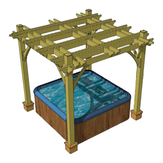
8x8 Spa Breeze Pergola
Assembly Manual
Outdoor Living Today
www.outdoorlivingtoday.com
Page 1
Revision 3.
Feb 18th/2015
sales@outdoorlivingtoday.com
Advertisement

Related Manuals for OLT Outdoor Living Today

Summary of Contents for OLT Outdoor Living Today
- Page 1 Dealers free of any liability for improper installation, maintenance and repair of any Outdoor Living Today products. In the event of a missing or broken piece, simply call the Outdoor Living Today Customer Support Line @ 1-888-658-1658 within 30 days of the delivery of your purchase.
-
Page 2: Packing Checklist
Packing Check List 8 x 8 Spa Breeze Pergola Check Off Parts When Unpacking from Pallet 3 LADDER SECTIONS Thank you for purchasing one of our Spa Breeze Pergola’s. Please take the time to identify all the parts prior to assembly. Parts Lists: Finished Size Specifications:... -
Page 3: Hardware Kit
8x8 SPA BREEZE PERGOLA HARDWARE PACKAGE Hardware Kit 2” (Provided) Stainless Note: screws and nails shown actual size. 2” 2” SS Square Drive Bit Finishing Nail 3” Lag Screw and Washer (16 each) 2 1/2” 4” Wooden Dowel (8) Tools Required (Not Provided) Wood Clamp 9/16”... - Page 4 Laying Out Your Footprint To determine the proper placement of your Posts and Footings, refer to footprint detail illustration on the left. Outside Post to Post measurements for the 8’x8’x Spa Breeze Pergola is 101” x 101”. Take diagonal measurements in both directions to confirm square.
- Page 5 Important - Western Red Cedar Lumber and Timbers will have surface splitting that occurs as lumber seasons and drys to the moisture content in your area. Splitting or “checking”, as it is referred to, can be 1/8” to 1/4” wide and can run several feet.
- Page 6 If Post Mount Hardware is installed, position bottom of posts in hardware. Secure post to post hardware with appropriate hardware such as bolts , lag bolts or a sufficient number of screws.(Hardware Not Supplied) ABU66 bracket shown. Lift, position and attach the second post/girder assembly to post hardware.
- Page 7 Carefully lower (Part C) Girder with Deep Notch Facing Down - 1 1/2” x 5 1/2” x 119” down into notch of (B) girders. Be careful not to twist the girder when positioning down into place. Lag screw girder to post. Drill shallow pilot hole first with 1/4”...
- Page 8 With stub joists positioned correctly on joist, attach each stub joist with 2 - 2 1/2” screws. Stub joists should be flush with top and bottom of joist with all notches facing down. There are two joist / stub joist assembly’s, complete both now.
- Page 9 On a flat surface, position Ladder Blocking (F) where marked on top edge of joist (D) and screw with 2 - 2 1/2” screws per end. Ladder blocking should be flush with top and bottom of joist with all notches facing down.
- Page 10 Notch slips onto girder. Carefully slide joist notches of ladder section onto girder. Try to align notches so they fall into place all at once. With notches of ladder section all sitting correctly on girder, slide section approximately 7” from post.
- Page 11 (H) Right Side There are 4 Left (G) and 4 Right Sided Corner Bracket. Corner Brackets (H). Corner Bracket Post Mounts - 3/4” x 4 1/2” x 10 1/2” (Part I) must be attached to the bottom end of each corner bracket before attaching to posts.
- Page 12 4” screws countersunk 1/2” below surface. Bracket Left sided spacer flush corner bracket. with bottom of girder. Important- Posts may need to be aligned so they are true and square to mount corner brackets correctly. Use a Level to determine correct post position. Lift completed left sided corner bracket up and align bottom of bracket spacer flush with bottom of girder.
- Page 13 Post Skirtings with Dado Cut (K) Post Skirting Caps (L) Skirting with cleat. Dado cut skirting. Post Skirtings with Cleat (J) Post mount bolts. Locate all Post Skirting pieces. Position 2 post skirtings around the base of post as shown above. Use 1 Post Skirting with Cleat - 1 1/2”...
- Page 14 Please call, write or email us at: proprietary notices contained the materials. No material may be Outdoor Living Today modified, edited taken United States Address Canadian Address context such that its use creates a false or 9393 287th Street P.O.