Table of Contents
Advertisement
Available languages
Available languages
Quick Links
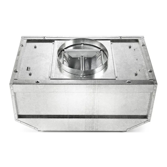
600 CFM AND 1200 CFM IN-LINE BLOWERS
VENTILATEURS EN LIGNE AVEC DÉBIT DE 600 PI³ ET
1200 PI³ POUR HOTTES D'ÉVACUATION
IN-LINE BLOWER SAFETY............................................................1
INSTALLATION REQUIREMENTS ................................................3
Tools and Parts ............................................................................3
Location Requirements ................................................................3
Venting Requirements ..................................................................4
Electrical Requirements ...............................................................5
INSTALLATION INSTRUCTIONS ..................................................6
Prepare Location ..........................................................................6
Make Electrical Connection .........................................................7
ASSISTANCE OR SERVICE ...........................................................9
In the U.S.A...................................................................................9
In Canada .....................................................................................9
WARRANTY...................................................................................10
We have provided many important safety messages in this manual and on your appliance. Always read and obey all safety
messages.
This is the safety alert symbol.
This symbol alerts you to potential hazards that can kill or hurt you and others.
All safety messages will follow the safety alert symbol and either the word "DANGER" or "WARNING."
These words mean:
WARNING
All safety messages will tell you what the potential hazard is, tell you how to reduce the chance of injury, and tell you what can
happen if the instructions are not followed.
IMPORTANT: READ AND SAVE THESE INSTRUCTIONS.
FOR RESIDENTIAL USE ONLY.
IMPORTANT : LIRE ET CONSERVER CES INSTRUCTIONS.
POUR UTILISATION RÉSIDENTIELLE UNIQUEMENT.
LI3ZDB/W10331013B
INSTALLATION INSTRUCTIONS
FOR RANGE HOODS
INSTRUCTIONS D'INSTALLATION
Table of Contents/Table des matières
IN-LINE BLOWER SAFETY
Your safety and the safety of others are very important.
DANGER
SÉCURITÉ DU VENTILATEUR EN LIGNE..............................11
EXIGENCES D'INSTALLATION...............................................13
Outils et pièces.......................................................................13
Exigences d'emplacement.....................................................13
Exigences concernant l'évacuation .......................................14
Spécifications électriques ......................................................15
INSTRUCTIONS D'INSTALLATION ........................................16
Préparation de l'emplacement...............................................16
Raccordement électrique.......................................................17
ASSISTANCE OU SERVICE.....................................................19
Au Canada..............................................................................19
GARANTIE.................................................................................20
You can be killed or seriously injured if you don't immediately
follow instructions.
You can be killed or seriously injured if you don't follow
instructions.
Advertisement
Table of Contents

Related Manuals for Amana UXI0600DYS


Summary of Contents for Amana UXI0600DYS
-
Page 1: Table Of Contents
IMPORTANT: READ AND SAVE THESE INSTRUCTIONS. FOR RESIDENTIAL USE ONLY. IMPORTANT : LIRE ET CONSERVER CES INSTRUCTIONS. POUR UTILISATION RÉSIDENTIELLE UNIQUEMENT. LI3ZDB/W10331013B FOR RANGE HOODS Table of Contents/Table des matières SÉCURITÉ DU VENTILATEUR EN LIGNE...11 EXIGENCES D’INSTALLATION...13 Outils et pièces...13 Exigences d’emplacement...13... -
Page 2: Read And Save These Instructions
IMPORTANT SAFETY INSTRUCTIONS WARNING: TO REDUCE THE RISK OF FIRE, ELECTRIC SHOCK, OR INJURY TO PERSONS, OBSERVE THE FOLLOWING: Use this unit only in the manner intended by the manufacturer. If you have questions, contact the manufacturer. Before servicing or cleaning the unit, switch power off at service panel and lock the service disconnecting means to prevent power from being switched on accidentally. -
Page 3: Installation Requirements
INSTALLATION REQUIREMENTS Tools and Parts Gather the required tools and parts before starting installation. Read and follow the instructions provided with any tools listed here. Tools needed Drill 1¼" (3 cm) drill bit " (0.5 cm) drill bit Pencil Wire stripper or utility knife Tape measure or ruler Pliers Caulking gun and weatherproof caulking compound... -
Page 4: Venting Requirements
The vent system must terminate to the outdoors. Do not terminate the vent system in an attic or other enclosed area. Do not use 4" (10.2 cm) laundry-type vent or wall caps. Use round, metal vent only. Rigid metal vent is recommended. -
Page 5: Electrical Requirements
Calculating Vent System Length To calculate the length of the system you need, add the equivalent feet (meters) for each vent piece used in the system. Vent Piece Equivalent Length 45° elbow 2.5 ft (0.8 m) 90° elbow 5.0 ft (1.5 m) The maximum equivalent vent lengths are: 10"... -
Page 6: Installation Instructions
INSTALLATION INSTRUCTIONS Before making cutouts, make sure there is proper clearance within the ceiling or wall for the exhaust vent. When cutting or drilling into the ceiling or wall, do not damage electrical wiring or other hidden utilities. Check that all installation parts have been removed from the shipping carton. -
Page 7: Make Electrical Connection
2. Drill 4 mounting pilot holes using a 3. Attach the in-line blower motor housing to the mounting location with four 6.3 x 60 mm mounting screws and washers. 4. If removed, reinstall the blower motor assembly and secure it with the screws previously removed. - Page 8 WARNING Electrical Shock Hazard Electrically ground blower. Connect ground wire to green and yellow ground wire in terminal box. Failure to do so can result in death or electrical shock. 8. Connect the green (or yellow/green) ground wire to the green/yellow ground wire (H) in the terminal box using UL listed wire connectors.
-
Page 9: Assistance Or Service
When calling for assistance or service, please know the purchase date and the complete model and serial number of your appliance. This information will help us to better respond to your request. If you need replacement parts If you need to order replacement parts, we recommend that you use only factory specified parts. -
Page 10: Warranty
WHIRLPOOL CORPORATION MAJOR APPLIANCE WARRANTY For one year from the date of purchase, when this major appliance is operated and maintained according to instructions attached to or furnished with the product, Whirlpool Corporation or Whirlpool Canada LP (hereafter “Whirlpool”) will pay for Factory Specified Parts and repair labor to correct defects in materials or workmanship. -
Page 11: Sécurité Du Ventilateur En Ligne
SÉCURITÉ DU VENTILATEUR EN LIGNE Votre sécurité et celle des autres est très importante. Nous donnons de nombreux messages de sécurité importants dans ce manuel et sur votre appareil ménager. Assurez-vous de toujours lire tous les messages de sécurité et de vous y conformer. Voici le symbole d’alerte de sécurité. -
Page 12: Importantes Instructions De Sécurité
IMPORTANTES INSTRUCTIONS DE SÉCURITÉ AVERTISSEMENT : POUR RÉDUIRE LE RISQUE D'INCENDIE, CHOC ÉLECTRIQUE OU DOMMAGES CORPORELS, RESPECTER LES INSTRUCTIONS SUIVANTES : Utiliser cet appareil uniquement dans les applications envisagées par le fabricant. Pour toute question, contacter le fabricant. Avant d'entreprendre un travail d'entretien ou de nettoyage, interrompre l'alimentation de la hotte au niveau du tableau de disjoncteurs, et verrouiller le tableau de disjoncteurs pour empêcher tout rétablissement accidentel de... -
Page 13: Exigences D'installation
EXIGENCES D’INSTALLATION Outils et pièces Rassembler les outils et composants nécessaires avant d’entreprendre l’installation. Lire et observer les instructions fournies avec chacun des outils de la liste ci-dessous. Outils nécessaires Perceuse Foret de 1¼" (3 cm) Foret de " (0,5 cm) Crayon Pince à... -
Page 14: Exigences Concernant L'évacuation
Le système d’évacuation doit décharger l’air à l’extérieur. Ne pas terminer le circuit d’évacuation dans un grenier ou dans un autre espace clos. Ne pas utiliser une bouche de décharge murale de 4" (10,2 cm) ou de bouche de décharge de 4" (10,2 cm) normalement utilisée pour un équipement de buanderie. -
Page 15: Spécifications Électriques
Calcul de la longueur effective du circuit d’évacuation Pour calculer la longueur effective du circuit d’évacuation nécessaire, additionner les longueurs équivalentes (en pieds ou mètres) de tous les composants utilisés dans le circuit. Composant Longueur équivalente Coude à 45° 2,5 pi (0,8 m) Coude à... -
Page 16: Instructions D'installation
INSTRUCTIONS D’INSTALLATION Avant d’effectuer des découpes, s’assurer que l’espace est suffisant sur le mur ou le plafond pour le conduit d’évacuation. Lors des opérations de découpe et de perçage dans un mur ou un plafond, veiller à ne pas endommager les câblages électriques ou autres canalisations intégrées. -
Page 17: Raccordement Électrique
3. Visser le logement du ventilateur en ligne à son emplacement avec quatre vis de montage 6,3 x 60 mm et rondelles. 4. Si l’ensemble moteur-ventilateur a été retiré, le réinstaller et le fixer avec les vis retirées auparavant. 5. Si la prise électrique du moteur a été débranchée, la rebrancher au connecteur de l’ensemble moteur-ventilateur. - Page 18 AVERTISSEMENT Risque de choc électrique Relier le ventilateur à la terre. Brancher le fil relié à la terre au fil vert et jaune relié à la terre dans la boîte de la borne. Le non-respect de ces instructions peut causer un décès ou un choc électrique.
-
Page 19: Assistance Ou Service
Lors d’un appel pour assistance ou service, veuillez connaître la date d’achat, le numéro de modèle et le numéro de série complets de l’appareil. Ces renseignements nous aideront à mieux répondre à votre demande. Si vous avez besoin de pièces de rechange Si vous avez besoin de commander des pièces de rechange, nous vous recommandons d’employer uniquement les pièces spécifiées par l’usine. -
Page 20: Garantie
GARANTIE DES GROS APPAREILS MÉNAGERS Pendant un an à compter de la date d'achat, lorsque ce gros appareil ménager est utilisé et entretenu conformément aux instructions jointes à ou fournies avec le produit, Whirlpool Corporation ou Whirlpool Canada LP (ci-après désignées “Whirlpool”) paiera pour les pièces spécifiées par l'usine et la main-d'œuvre pour corriger les vices de matériaux ou de fabrication.
Need help?
Do you have a question about the UXI0600DYS and is the answer not in the manual?
Questions and answers