Table of Contents

Related Manuals for Carrier 30PA 90


Summary of Contents for Carrier 30PA 90
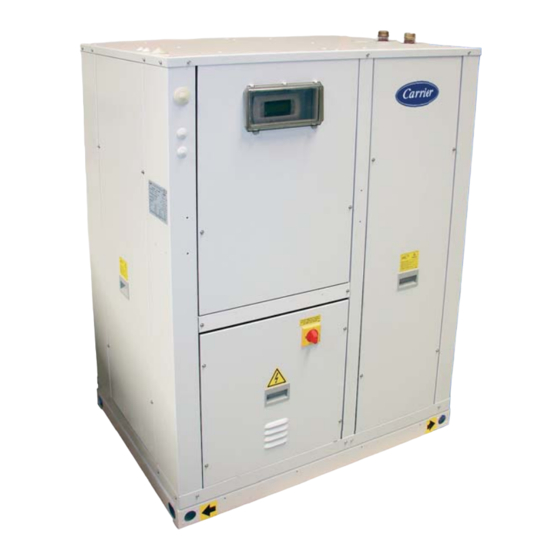
- Page 1 M A I N T E N A N C E I N S T R U C T I O N S Ductable air-cooled scroll chillers 30PA 90-180 Nominal cooling capacity 17 - 36 kW Translation of the original document 80057, 09.2018...
-
Page 2: Table Of Contents
CONTENTS 1 - INTRODUCTION .................................... 3 2 - SAFETY ADVISE ................................... 3 3 - OPERATION LIMITS..................................4 4 - AVAILABLE CONFIGURATIONS ..............................4 5 - UNIT IDENTIFICATION ................................. 5 6 - TRANSPORT AND HANDLING ..............................5 Transport ...................................... 5 Discharging of the unit .................................. 5 Placement on site .................................. -
Page 3: Introduction
1 - INTRODUCTION The 30PA cooling only are compact outdoor air/water units. ■ The units comply with European Directives: Available in two versions: - Machinery Directive 2006/42/EC (MD) • STD (Standard) - Electromagnetic Compatibility Directive 2014/30/EU (EMC) • HEE (High Energy Effi ciency) - Low Voltage Directive 2014/35/EU (LVD) These units have been made for operation indoor, off... -
Page 4: Operation Limits
3 - OPERATION LIMITS Cooling mode Series Water (outlet T.) Max. Min. Max. Min. 30PA 46ºC 18ºC 12ºC 5ºC With control of the condensation pressure operating up to -15ºC. Minimum outlet temperature. With the option of glycol water for ... -
Page 5: Unit Identification
PSmax(BP\LP) Temp. Max./ IP Peso\Poids\Weight NoBo Maximum service pressure in the high pressure side (R-410A = 42 bar) CARRIER SCS Fabricante\Fabricant\Manufacturer: Route de Thil Compañía Industrial de Aplicaciones Térmicas, S.A. 01122 Montluel-FRANCE P. Ind. Llanos de Jarata s/n. 14550 Montilla-SPAIN... -
Page 6: Placement On Site
6 - TRANSPORT AND HANDLING Placement on site Centre of gravity coordinates Once the unit is discharged, it must be freed from the transport Centre of gravity Weight (mm) supports so that the inserts available for the silent-blocks can be 30PA empty (kg) -
Page 7: Anchorage For Silent-Blocks
7 - LOCATION AND ASSEMBLING Anchorage for silent-blocks Radiated sound power level Measurement conditions: ducted discharge and return. For nominal Distances (mm) Reactions in the supports (kg) operating conditions EN 14511 – Acoustic power reference: 10E-12 30PA W, tolerance of ±2 dB (partial charge of ±4 dB). Weight in service STD version... -
Page 8: Checking Before Commissioning
8 - CHECKING BEFORE COMMISSIONING NOTE: Under no circumstance should the unit be started without having read the brochure completely. Electrical connections Installation norms 30PA electronic control In order to establish the unit's electric power supply (cable inlet, The 30PA control is basically comprised of a μPC SMALL control calculation of the lead section, protections etc.), refer to: board, a pGD1 graphic terminal, a TCO user terminal (optional for remote control) and sensors. -
Page 9: Checks In The Centrifugal Fan: Std Version
8 - CHECKING BEFORE COMMISSIONING Checks in the centrifugal fan: STD version It is essential to tension the belts using the “Defl ection test” described below: ■ Before commissioning, check the blade rotation direction and ■ The belt tension must be checked and corrected using a suitable that the axis turns without strokes nor vibrations measuring instrument (tensiometer or dynamometer) ■... -
Page 10: Air Ducts Connections
8 - CHECKING BEFORE COMMISSIONING Air ducts connections Return ducts For units designed for installation indoors with ducted supply and Without fi lters (mm) With fi lters (mm) STD version return in the outdoor circuit, it is advisable to have the following recommendations: 90STD / 100STD ■... -
Page 11: Hydraulic Connections
8 - CHECKING BEFORE COMMISSIONING Hydraulic connections Installation water volume Evaporator operating limits The curves represent the minimum and maximum admissible Minimum installation volume temperature increases based on the outlet (discharge) The electronic control for these units incorporates an auto-adaptive temperature, for both pure water and glycol water. - Page 12 8 - CHECKING BEFORE COMMISSIONING If more amount is needed, it must be exactly the same mixture Water content Concentration (mg/l) AISI 316 Copper as the product initially used. Organic substances The following table and curves feature the minimum glycol percentages required for the installation in accordance with the <...
- Page 13 8 - CHECKING BEFORE COMMISSIONING ■ It is advisable to use fl exible hoses for connecting the piping to the unit in order to reduce the transmission of vibrations to the building to the greatest degree. It is mandatory to assemble hoses if the unit is installed over shock absorbers.
-
Page 14: Condensate Drain Connection
8 - CHECKING BEFORE COMMISSIONING Condensate drain connection In 30PA units, the condensate drain pan includes a 3/4” M bronze, - The drain piping must be slightly sloped to ease circulation bleeding trunk for draining condensates. towards the drain. - The original diameter of the piping must be respected. No Attention: With low outdoor temperatures, the electrical heater- reduction can be made. -
Page 15: Air Fi Lter
9 - OPTIONS Cooling recovery circuit No. of Servos per Damper 30PA Assembly dampers damper width The system consists in a hot water supplying by an heat recovery system on the compressor(s) discharge gas, on an auxiliary 90STD to 180STD desuperheater exchanger. - Page 16 9 - OPTIONS Technical characteristics of the recovery circuit Hydraulic connections of the recovery circuit STD version 30PA 100 120 160 180 Recovery capacity (kW) Nominal water fl ow (m 0,38 0,45 0,53 0,70 0,76 Pressure drop (m.w.c.) 0,06 0,09 0,17 0,30 0,36 Cooling capacity (kW) 17,8 21,3 25,3 33,0 36,2 Power input (kW)
-
Page 17: Safety Elements
10 - SAFETY ELEMENTS Low pressure pressostat Water circulation control Connected to the compressor suction, it will A diff erential pressure switch detains the operation of the unit when stop its operation when the pressure at that it does not detect water circulation. point goes down below the tare value (caused by obstructions in the circuit, excessive dirt in the fi... -
Page 18: Commissioning
11 - COMMISSIONING Checks prior to commissioning Adjustment of the water fl ow ■ It is advisable to make a complete sketch of the installation including the location of the unit and all the components used ■ The fi lling of the hydraulic circuit is then carried out: in the hydraulic circuit (cut-off... -
Page 19: Possible Problems At Commissioning
11 - COMMISSIONING Control of the refrigerant load ■ When starting the compressor, check the subcooling and - Completely empty the unit using a specifi c recovery unit for overheating and thus verify is the refrigerant load is appropriate R-410A and repair the leak. to the operation conditions. -
Page 20: Operational Checks
11 - COMMISSIONING Operational checks Cooling MODE Check the unit operation by verifying the electronic control and Suction pressure the safety devices. Suction temperature (1) ºC Compressor It is also recommendable to create a report, taking note of the Condensation pressure date, which includes the following information: Condensation temperature (2) ºC... - Page 21 12 - MAINTENANCE Mesh fi lter Servomotor (optional) ■ It is also necessary to install a fi lter in the hydraulic power In units with a condensation supply to the unit in order to prevent clogging of the plate pressure regulation damper exchanger.
- Page 22 12 - MAINTENANCE Refrigerant ■ Make vacuum and next, reload the gas into the unit according to load data provided in the in the table of paragraph “Refrigerant” Only qualifi ed personnel must perform a periodic leak testing, in and in the unit’s data plate. accordance with the regulation (EC) No.
-
Page 23: Control And Analysis Of Breakdowns
13 - CONTROL AND ANALYSIS OF BREAKDOWNS Symptom Cause Solution Evaporation pressure very high in relation a) Charge excess a) Collect refrigerant with the air or water inlet b) High water temperature b) Verify overheating c) Compressor suction not air tight c) Verify compressor state and replace d) Cycle reversing valve in middle position d) Check that the valve is not clogged. -
Page 24: Final Shutdown
14. FINAL SHUTDOWN Shutting down Materials to be recovered for recycling Separate the units from their energy sources, allow them to cool ■ Steel then drain them completely. ■ Copper ■ Aluminium ■ Plastics Recommendations for disassembly ■ Polyurethane foam (insulation) Use the original lifting equipment. -
Page 25: Annex I: Quick Overview Of The Installation
ANNEX I: QUICK OVERVIEW OF THE INSTALLATION Air-cooled chillers Installer Telephone Responsible for installation and/or commissioning Installation / work reference Address Unit Unit model Serial number Date for commissioning Installation sketch and units location... - Page 26 ANNEX I: QUICK OVERVIEW OF THE INSTALLATION SÍ Electrical POWER ......................connections • Provisional voltage _____ V Available power_____kW • Final Voltage _____ V + T + N • Line protection type Fuse Curve ____________ Automatic Curve ____________ CONTROL • On / off external control ................•...
- Page 28 Order No.: 10057, 09.2018. Supersedes order No.: 07.2018 Manufactured for CARRIER in Spain. Manufacturer reserves the right to change any product specifi cations without notice. Printed in the European Union.
Need help?
Do you have a question about the 30PA 90 and is the answer not in the manual?
Questions and answers