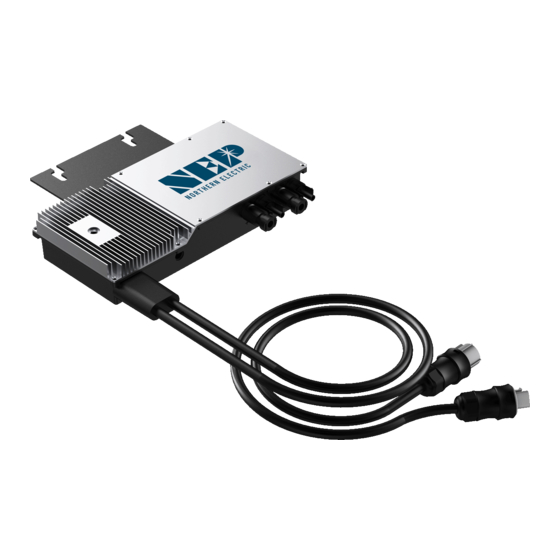
NEP BDM-600 Installation And Operation Manual
North american version dual module microinverter
Hide thumbs
Also See for BDM-600:
- Installation and operation manual (22 pages) ,
- Installation & user manual (26 pages) ,
- Quick installation manual (2 pages)
Table of Contents
Advertisement
Quick Links
USA
Address: 2570 N. First Street, Suite 200, San Jose, CA 95131
TEL: +1 888-598-9901
Japan
Address: 812-0011 福岡市博多区博多駅前 3-10-24 藤井ビル 1F
TEL: +81 092-433-3252
FAX: +81 092-433-3171
China
Address: No.1 Anhe Rd Tsingtao Export Processing Zone, Tsingtao, China 266113
TEL: +86 532 87963900
FAX: +86 532 81100917
Email: info@northernep.com
Web: h�p://www.northernep.com
h�p://www.nep-japan.com
h�p://www.micro-inverter.jp
Rev. 2017-01-12
Installa�on and Opera�on Manual
North American Version
BDM-600
Dual Module Microinverter
l
SAA
152167
Advertisement
Table of Contents

Summary of Contents for NEP BDM-600
- Page 1 Installa�on and Opera�on Manual North American Version BDM-600 Dual Module Microinverter Address: 2570 N. First Street, Suite 200, San Jose, CA 95131 TEL: +1 888-598-9901 Japan Address: 812-0011 福岡市博多区博多駅前 3-10-24 藤井ビル 1F TEL: +81 092-433-3252 FAX: +81 092-433-3171 China Address: No.1 Anhe Rd Tsingtao Export Processing Zone, Tsingtao, China 266113...
-
Page 2: Table Of Contents
1.3 How to Use This Manual 1.4 Label 2. SAFETY INSTRUCTION 3. FCC COMPLIANCE 4. DESIGN 5. PARTS NEEDED 5.1 NEP Parts 5.2 Addi�onal Parts and Tools Requires 5.3 Lightning and Surge Suppression 5.4 Shipping Informa�on 6. INSTALLATION 6.1 Pre-installa�on 6.2 Installa�on Steps... -
Page 3: Company Profile
COMPANY PROFILE Northern Electric & Power Inc. (NEP) is an interna�onal supplier of cu�ng-edge clean energy technologies headquartered in the United States. The company maintains facili�es both here and abroad, including a more than 18 acre site in the Tsingtao Export Processing Zone and has more than 650,000 square feet of building space. -
Page 4: Introduction
REGULATIONS. THIS PROTECTION IS LIKELY TO INCLUDE RESIDUAL CURRENT DEVICES, EARTH FAULT MONITORS The BDM-600 is designed to support either one or two 60 or 72 cell modules in AND CIRCUIT BREAKERS. THIS PRODUCT MAY CAUSE AC CURRENT WITH A DC COMPONENT. IF A RESIDUAL grid-�ed PV system consists of PV panels, grid-�ed inverter and junc�on boxes. -
Page 5: Design
5.4 Shipping Informa�on 5.1 NEP Parts The BDM-600 Ships six (6) to a box with each box measuring approximately 18” x In addi�on to the micro inverters, you’ll need the following parts from NEP: 13.5” x 16”and weighing 57 lbs. A typical pallet contains 27 boxes. -
Page 6: Installa�On Steps
ROOF AND THE BOTTOM OF THE BDM-600 AND BETWEEN THE BACK OF THE PV MODULE MUST BE SOURCED FROM A 20A MAXIMUM BREAKER. AND THE TOP OF THE BDM-600. DO NOT PLACE THE BDM-600 IN A LOCATION SUBJECT TO Install a protec�ve end cap on the open female AC connector on the last DIRECT SUNLIGHT. -
Page 7: Step 3 - Install The Ac Branch Circuit Junc�On Box
PV module to the positively marked DC connector (female socket) of the BDM-600. Next, do the same for the second set of DC connectors from the second module. Repeat for all remaining PV modules using one BDM-600 for each set of modules. -
Page 8: Commissioning
ENSURE THAT ALL AC AND DC WIRING IS CORRECT. ENSURE THAT NONE OF THE In case of a fault, the BDM-600 enters a protec�ve mode and stops outputing power. AC AND DC WIRES ARE PINCHED OR DAMAGED AND THAT ALL JUNCTION BOXES ARE The fault message is usually sent to a connected BDG-256 gateway through the PROPERLY SEALED CLOSE. - Page 9 WARNING: ALWAYS DISCONNECT AC POWER BEFORE DISCONNECTING PV MODULE WIRES FROM THE BDM-600. THE AC CONNECTOR OF THE FIRST BDM-600 IN A BRANCH CIRCUIT IS To ensure the BDM-600 is not disconnected from the PV modules under load, SUITABLE AS A DISCONNECTING MEANS ONCE THE AC BRANCH CIRCUIT BREAKER IN THE adhere to the following disconnec�on steps in the order shown:...
-
Page 10: Specifications
10. SPECIFICATIONS *per IEEE1547A MODEL BDM-600 Max Recommended PV Power(Wp) 340 x 2 Max DC Open Circuit Voltage(Vdc) INPUT(DC) Max DC Input Current (Adc) 12 x 2 MPPT Tracking Accuracy >99.5% MPPT Tracking Range(Vdc) 22-55 Peak AC Output Power(Wac) Rated AC Output Power(Wac) -
Page 11: Warranty And Product Information
NEP will not be responsible for any defect in or damage to: a) the 11. WARRANTY AND PRODUCT INFORMATION product if it has been misused, neglected, improperly installed, physically damaged or altered, either internally or externally, or damaged from improper use or use in an unsuitable environment;... - Page 12 For the informa�on on our warranty terms and condi�ons, please see our website: www.northernep.com/en All fields must be completed in order to process claim. Customer Signature: Date: *All rights reserved by NEP. This informa�on is subject to changes without no�ce.
- Page 13 TEL: +1 888-598-9901 Japan Address: 812-0011 福岡市博多区博多駅前 3-10-24 藤井ビル 1F TEL: +81 092-433-3252 FAX: +81 092-433-3171 China Address: No.1 Anhe Rd Tsingtao Export Processing Zone, Tsingtao, China 266113 TEL: +86 532 87963900 FAX: +86 532 81100917 Email: info@northernep.com Web: h�p://www.northernep.com h�p://www.nep-japan.com h�p://www.micro-inverter.jp...


Need help?
Do you have a question about the BDM-600 and is the answer not in the manual?
Questions and answers