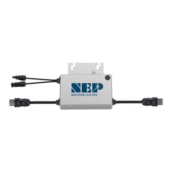
Table of Contents
Advertisement
Quick Links
USA
Address: 1781 Riverview Ave., Tracy, CA 95377
Australia
Address: 9 Meander Grove, Cameron Park, NSW2285
China
Address: No.1 Anhe Rd Tsingtao Export Processing Zone, Tsingtao, China 266113
TEL: +86 532 87963900
FAX: +86 532 81100917
Installa�on and Opera�on Manual
BDM-250-240A
BDM-250-208A
BDM-250-AU
BDM-250-EU
BDM-250-LV
SAA
N136
122309
Advertisement
Table of Contents

Subscribe to Our Youtube Channel
Summary of Contents for NEP BDM-250-240A
- Page 1 Installa�on and Opera�on Manual BDM-250-240A BDM-250-208A BDM-250-AU BDM-250-EU BDM-250-LV Address: 1781 Riverview Ave., Tracy, CA 95377 Australia Address: 9 Meander Grove, Cameron Park, NSW2285 China Address: No.1 Anhe Rd Tsingtao Export Processing Zone, Tsingtao, China 266113 N136 TEL: +86 532 87963900...
-
Page 2: Table Of Contents
CONTENTS COMPANY PROFILE 1. INTRODUCTION 1.1 Prefix 1.2 Grid-�ed PV System 1.3 How to Use This Manual 1.4 Label 2. SAFETY INSTRUCTION 3. FCC COMPLIANCE 4. INSTALLATION Parts Included Other Parts and Tools Required Lightning Surge Suppression Installa�on Procedure Step 1 - Install the AC Branch Circuit Junc�on Box Step 2 - A�ach the BDM-250 to the Racking Step 3 - Connect the BDM-250 Wiring Harnesses Step 4 –... -
Page 3: Company Profile
COMPANY PROFILE Northern Electric & Power Inc. (NEP) was founded in the United States and has manufacturing and R&D facili�es in China. The mission of the company is to develop cu�ng-edge clean energy technologies and provide state-of-the-art solar inverter products to its customers. The first round of investment to the company was US$20 Million, with a planned total investment of US$50 Million. -
Page 4: Introduction
WARNING: PLEASE READ THIS MANUAL BEFORE INSTALLATION. ANY DAMAGE TO THE PRODUCT DUE TO NOT Dear customer, thank you for choosing the BDM-250 micro inverter from NEP. FOLLOWING THIS MANUAL IS NOT COVERED BY THE WARRANTEE. We hope you will find our products meet your need for renewable energy. -
Page 5: Installation
Step 1 - Install the AC Branch Circuit Junc�on Box Since the NEP Limited Warranty does not cover “acts of God” such as lightning 1. Measure service entrance conductors to confirm AC service at the site. -
Page 6: Step 2 - A�Ach The Bdm-250 To The Racking
1. Mark the approximate centers of each PV module on the racking system. Evaluate BDM-250-240A and BDM-250-208A, the L1 wire (red), L2 wire (black) and the loca�on of the micro inverter with respect to the PV module junc�on box or any neutral wire (blue) in the AC cable should be connected to the corresponding other obstruc�ons. -
Page 7: Step 4 - Ground The System
BDM-250 connec�on Map is a diagramma�c representa�on of the physical conductor. If you are not using grounding washers to ground the BDM-250 loca�on of each BDM-250 in your PV installa�on. The virtual array in NEP micro chassis as described in step2, route a con�nuous GEC through each of the inverter gateway BDG-256 is created from the map you create. -
Page 8: Commissioning
6. OPERATING INSTRUCTIONS 5. COMMISSIONING The BDM-250 is powered on when sufficient DC voltage from the module is applied. WARNING: The status LED will start flashing a�er sufficient DC power is applied as an indica�on CONNECT BDM-250 TO THE ELECTRICAL UTILITY GRID ONLY AFTER RECEIVING that the BDM-250 is live. - Page 9 6. Check the DC connec�ons between the BDM-250 and the PV module. BDM-250 comes with two oppositely sexed DC connectors. 7. If the problem persists, please call customer support at NEP. b) First connect the posi�ve DC wire from the PV module to the posi�vely WARNING: DO NOT ATTEMPT TO REPAIR THE BDM-250;...
-
Page 10: Specification
Vmax PV (absolute maximum) (Vdc) PV Input Opera�ng Voltage Range (Vdc) 22-55 INPUT(DC) Maximum Opera�ng PV Input Current (Adc) MODEL BDM-250-240A BDM-250-208A MPPT Tracking Accuracy >99.5% Max Recommended PV Power (Wp) Isc PV (absolute maximum) (Adc) Maximum Inverter Backfeed Current to the Array (Adc) -
Page 11: Warranty And Production Information
What does this warranty not cover? OTHER Display LED LIGHT Claims are limited to repair and replacement or if in NEP's discre�on that is not PARAMETERS Communica�ons POWERLINE possible, reimbursement up to the purchase price paid for the product. NEP will be... -
Page 12: Warranty Card
Warranty Card does not apply to and NEP will not be responsible for any defect in or damage to: a) the product if it has been misused, neglected, improperly installed, physically Customer Informa�on damaged or altered, either internally or externally, or damaged from improper Name: use or use in an unsuitable environment;... - Page 13 Add:1781 Riverview Ave., Tracy, CA 95377 Australia Address: 9 Meander Grove, Cameron Park, NSW2285 China Add: No.1 Anhe Rd Tsingtao Export Processing Zone, Tsingtao, China 266113 TEL: +86 532 87963900 FAX: +86 532 81100917...


Need help?
Do you have a question about the BDM-250-240A and is the answer not in the manual?
Questions and answers